


Drives
Description Spare part number
16X SATA DVD±RW drive 660408-001
16X SATA DVD-ROM drive 581599-001
Blu-ray BD-RW SuperMulti DL Drive 656792-001
1 TB, 7200 rpm SATA hard drive 636930-001
500 GB, 7200 rpm, 2.5-inch, self-encrypting (SED), SATA hard drive 696442-001
500 GB, 7200 rpm SATA hard drive 636929-001
250 GB, 7200 rpm SATA hard drive 636927-001
256 GB Solid State Drive (SSD), self-encrypting (SED), SATA 6.0 680020-001
180 GB Solid State Drive (SSD), SATA 6.0
160 GB Solid State Drive (SSD), SATA 3.0 646809-001
128 GB Solid State Drive (SSD), SATA 2.0 665961-001
120 GB Solid State Drive (SSD), SATA 2.0 661841-001
20 GB Solid State Drive (SSD), SATA 683305-001
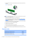
When installing drives, follow these guidelines:
●
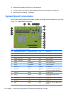
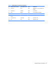
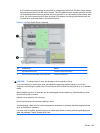
The primary Serial ATA (SATA) hard drive must be connected to the dark blue primary SATA
connector on the system board labeled SATA0. If you are adding a second hard drive, connect it
to the light blue connector on the system board labeled SATA1.
●
Connect the first SATA optical drive to the white SATA connector on the system board labeled
SATA2. If you are adding a second optical drive connect it to the black SATA connector on the
system board labeled ESATA. If the ESATA connector is already populated, connect the second
optical drive to the light blue connector on the system board labeled SATA1.
●
Connect an optional eSATA adapter cable to the black SATA connector on the system board
labeled ESATA.
●
Connect a media card reader USB cable to the USB connector on the system board labeled
MEDIA.
●
The power cable for the SATA optical drives is a two-headed cable this is plugged into the
system board with the first connector routed to the top 5.25-inch bay and the second connector
routed to the bottom 5.25-inch bay.
●
The power cable for the SATA hard drives is a two-headed cable this is plugged into the system
board with the first connector routed to the bottom 3.5-inch bay and the second connector routed
to the top 3.5-inch bay.
●
The system does not support Parallel ATA (PATA) optical drives or PATA hard drives.
●
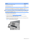
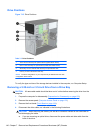
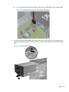
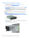
You must install guide screws to ensure the drive will line up correctly in the drive cage and lock
in place. HP has provided extra guide screws for the drive bays (four 6-32 isolation mounting
guide screws and eight M3 metric guide screws), installed on the side of the drive bays. The
138 Chapter 7 Removal and Replacement Procedures Microtower (MT) Chassis