


9
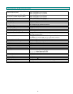
CAT5 Cable to
Local Unit
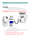
Green Power LED
Y
ellow CommunicationLED
(Front View)
NTI
R
Network Technologies Inc
XTENDEX
USB
-
+
ST-C5USBV-300 Remote Unit
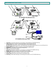
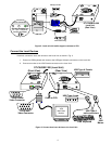
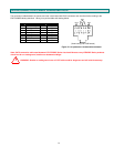
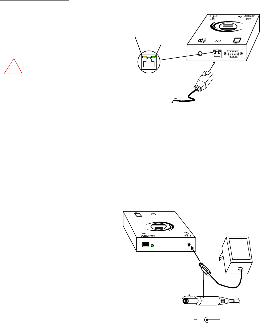
Connect the CAT5 cable
Connect the CAT5 cable to the “CAT5” port on the rear of
the Remote Unit (see Fig. 8). (If an RJ45 wall outlet is
being used, connect the other end of the extension cable
to it.) When properly inserted the cable end should snap
into place.
WARNING: Never connect the ST-C5USBV-300
Extender to an Ethernet card, Ethernet router,
hub or switch or other Ethernet RJ45 connector
of an Ethernet device. Damage to devices
connected to the Ethernet may result.
Figure 8- Connect CAT5 cable to the Remote Unit
Plug-in and Boot Up
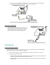
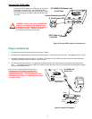
1. Plug the power cord(s) from the monitor(s) into power outlet(s).
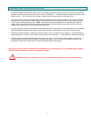
2. Connect the AC adapter power connectors to the 9VDC ports on the Remote and Local Units. (AC adapter shown in Fig. 9)
3. Plug the AC adapters into power outlets. The “Power” LED (Green) on the CAT5 connector of each unit should illuminate,
indicating that a proper power connection has been made.
4. Turn ON the CPU and monitor(s). The CPU and monitor(s) should each react as if they were directly connected to each
other. The yellow communication LEDs on the Remote and Local Units (see Fig. 8) should blink indicating there is proper
communication between them.
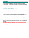
Note: A loss of signal (blank screen) may be
experienced for an instant during the auto-
compensation process after powering-up (ST-
C5USBVA model only). This may also occur if the
XTENDEX senses a loss of or weak signal connection
in the CAT5 cable.
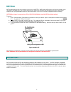
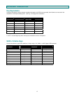
Figure 9- Connect AC adapters
!
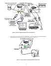
9 VDC
Adapter
ADAPTER
Barrel
(Inside
barrel)
(Outside
barrel)
Power Connector
2.1 mm x 5.5 mm Female
9VDC @ 1.0A OUTPUT
XTENDEX
USB
NTI
R
Network Technologies Inc
(Rear View)
-
+
ST-C5USBV-300
Remote Unit