


ii
Table of Contents
Introduction......................................................................................................................................................................1
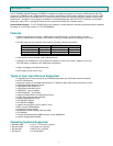
Features.......................................................................................................................................................................1
Types of User Input Devices Supported:.....................................................................................................................1
Operating Systems Supported ....................................................................................................................................1
Limitations....................................................................................................................................................................2
Materials..........................................................................................................................................................................2
Features and Functions...................................................................................................................................................3
Preparation for Installation ..............................................................................................................................................4
Installation .......................................................................................................................................................................5
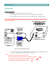
The Local Unit..............................................................................................................................................................5
Connect to the CPU..................................................................................................................................................5
Connect the Local Devices.......................................................................................................................................6
Connect the CAT5 Cable..........................................................................................................................................7
The Remote Unit..........................................................................................................................................................7
Connect the Remote Devices...................................................................................................................................7
Connect the CAT5 cable...........................................................................................................................................9
Plug-in and Boot Up.....................................................................................................................................................9
Command Mode............................................................................................................................................................10
MAC Mode.................................................................................................................................................................11
DDC Support.................................................................................................................................................................11
Common Applications ...................................................................................................................................................12
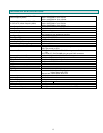
Technical Specifications................................................................................................................................................13
Interconnection Cable Wiring Method...........................................................................................................................14
Keyboard Translation ....................................................................................................................................................15
Key Equivalents.........................................................................................................................................................15
SUN’s 16 Extra Keys .................................................................................................................................................15
Troubleshooting.............................................................................................................................................................17
Index..............................................................................................................................................................................18
Warranty Information.....................................................................................................................................................18
Table of Figures
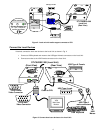
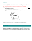
Figure 1- Connect the Local Unit to a CPU........................................................................................................................................5
Figure 2- Local unit with audio support connects to CPU ..................................................................................................................6
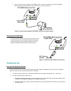
Figure 3- Connect local user devices to the Local Unit......................................................................................................................6
Figure 4- Connect stereo speakers to XTENDEX Local Unit with audio support...............................................................................7
Figure 5- Connect the CAT5 cable to the Local Unit..........................................................................................................................7
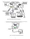
Figure 6- Connect the Monitor and Devices to the Remote Unit........................................................................................................8
Figure 7- Connect remote self-powered speakers to Remote Unit ....................................................................................................8
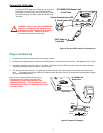
Figure 8- Connect CAT5 cable to the Remote Unit............................................................................................................................9
Figure 9- Connect AC adapters .........................................................................................................................................................9
Figure 10- MAC LED........................................................................................................................................................................11
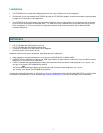
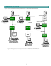
Figure 11- Examples of common applications for the ST-C5USBV-300 USB KVM Extender..........................................................12
Figure 12- Pin positions in female RJ45 connector..........................................................................................................................14
Figure 13- Keyboard Layouts...........................................................................................................................................................16