


82
4 Summary of the HP/Phoenix BIOS
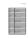
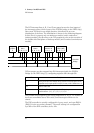
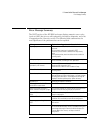
BIOS Addresses
DMA Channel Controllers
Only “I/O-to-memory” and “memory-to-I/O” transfers are allowed.
“I/O-to-I/O” and “memory-to-memory” transfers are disallowed by the
hardware configuration.
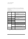
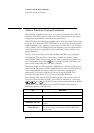
The system controller supports seven DMA channels, each with a page
register used to extend the addressing range of the channel to 16 MB. The
following table summarizes how the DMA channels are allocated.
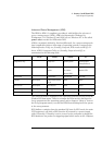
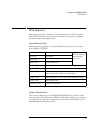
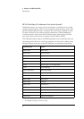
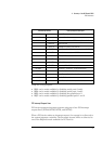
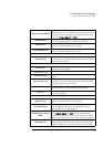
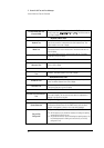
Interrupt Controllers
The system has two 8259A compatible interrupt controllers. They are
arranged as a master interrupt controller and a slave that is cascaded
through the master.
The following table shows how the master and slave controllers are con-
nected. The Interrupt Requests (IRQ) are numbered sequentially, starting
with the master controller, and followed by the slave.
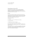
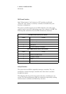
First DMA controller (used for 8-bit transfers)
Channel Function
0 Available
1 SoundBlaster or ECP mode for parallel port
2 Flexible disk I/O
3 ECP mode for parallel port or SoundBlaster
Second DMA controller (used for 16-bit transfers)
Channel Function
4 Cascade from first DMA controller
5 SoundBlaster or Available
6 Available
7 Available or SoundBlaster