


BIOS Overview
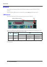
32 XE320 product description
BIOS Addresses
This section provides a summary of the main features of the HP system BIOS.
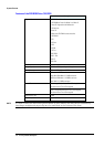
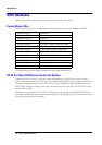
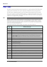
System Memory Map
Reserved memory used by accessory boards must be located in the area from C8000h to EFFFFh.
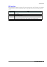
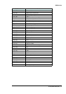
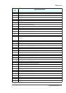
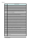
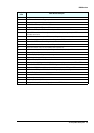
HP I/O Port Map (I/O Addresses Used by the System)
Peripheral devices, accessory devices and system controllers are accessed via the system I/O space,
which is not located in system memory space. The 64KB of addressable I/O space comprises 8-bit and 16-
bit registers (called I/O ports) located in the various system components. When installing an accessory
board, ensure that the I/O address space selected is in the free area of the space reserved for accessory
boards (100h to 3FFh).
Although the Setup program can be used to change some of the settings, the following address map is
not completely BIOS dependent, but is determined partly by the operating system. Note that some of the
I/O addresses are allocated dynamically.
0000 0000 - 0000 03FF Real-mode IDT
0000 0400 - 0000 04FF BIOS Data Area
0000 0500 - 0009 FC00 Used by OS
0009 FC00 - 0009 FFFF Extended BIOS Data Area
000A_0000 - 000B_FFFF Video RAM or SMRAM (not visible unless in SMM)
000C 0000 - 000C 7FFF Video ROM
000C 8000 - 000E 0000 Adapter ROM, RAM, memory-mapped registers
000E 0000 - 000F FFFF System BIOS (Flash/Shadow)
10 0000 - FF FFFF Memory (1MB to 16MB)
100 0000 - 1FF FFFF Memory (16MB to 32MB)
200 0000 -3FF FFFF Memory (32MB to 64MB)
400 0000 -1FFF FFFF Memory (64MB to 1.5GB)
1
1.The last MB of memory in this area is used as Unified Memory Architecture (UMA) embedded memory.
FFF80000 - FFFF FFFF 512KB BIOS (Flash)