


2-2 Removal and Replacement Technology Code IC)
Disassembly Flowchart
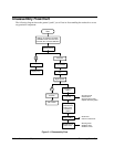
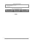
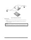
The following diagram shows the general “paths” you will use in disassembling the notebook to access
any particular component.
Figure 2-1. Disassembly Flow
Start
Battery, AC adapter, secondary
SDRAM module, mini-PCI card,
hard disk drive, DVD/CD-RW drive
Keyboard cover
Keyboard
B
Left speaker
Right speaker
• Docking doors
• PCMCIA doors
• PCMCIA socket
A
Display assy
Heatsink
CPU module
Modules on
path A
If removing
motherboard or
bottom case,
modules on
path B
Top case
Hinge saddles
Motherboard or
bottom case
• Audio PCA
• Volume control PCA
• CD player PCA
• Infrared PCA
• Hard disk drive guide
• Optical disk drive guides
Primary SDRAM
Fan