


ENGLISH
3
INSTALLATION INSTRUCTIONS
■ No stand is provided with this product. When installing the monitor, use the
optional Desk-top Stand (CMPAD05), Wall Mount Unit (horizontal-mount
CMPAK04 or CMPAK05, vertical/horizontal-mount CMPAK14), or Ceiling
Mount Unit (CMPAT04).
The Desk-top Stand has been used for the illustrations in this manual.
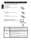
Installation
• Use one of the special mount units to install this product. A mount of insufficient
strength or inadequate design can cause overturning or dropping and result in fire,
electrical shock or injury. Please note that our company assumes absolutely no
responsibility for personal injuries or property damage caused by use of other
mount units or improper installation.
•
Installation of the wall mount unit and ceiling mount unit can be dangerous, so do not
attempt this work yourself. Ask your dealer to provide the name of a qualified installer.
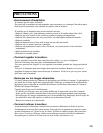
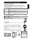
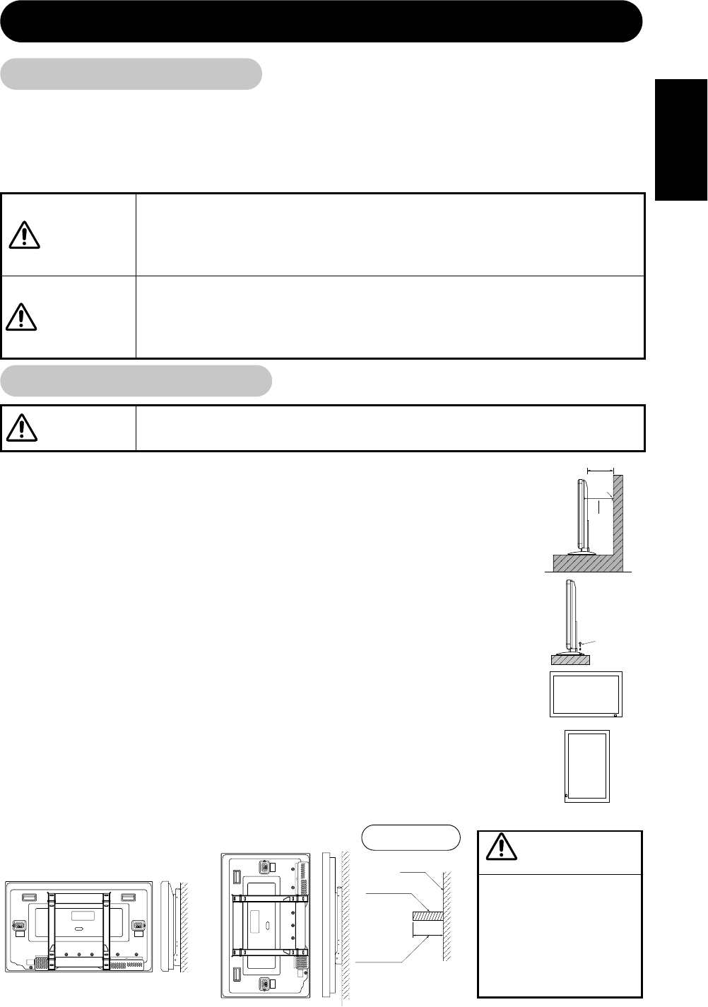
• In order to prevent an internal temperature increase, maintain a space of 10cm (4
inches : For a desktop set-up) or more between the sides and other objects such as
walls, etc., so that the ventilation holes are not blocked.*
WARNING
CAUTIONS
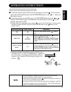
Cord
or
chain
Clamp
10cm (4 inches) or more*
Two places
Wood screw
Securing to a wall or pillar
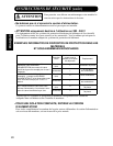
1)Using a commercially available cord, chain and clamp, secure the set to a firm wall or
pillar.
Securing desktop
1)Using wood screws (two), fasten the set to the clamping screw holes on the rear of the
stand as shown.
2)Using commercially available wood screws, secure the set firmly in position.
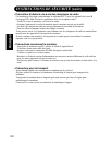
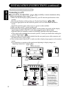
Using the optional vertical-mount unit (CMPAK14)
Using the optional wall-mount unit (CMPAK14) allows set to mount on wall surfaces as
shown at right.
1) Make at least four sets of commercial anchor bolts and screws available to meet various kinds of
walls to mount on.
2) Read the instructions supplied with the wall-mount unit carefully to optimally locate the plasma
display on a wall surface.
3) Prepare the wall surface for anchoring and drilling as needed, as shown in the sketches.
• Make sure that an adequate wall surface strength and a screw holding strength are available.
Anti-tumble measures
• Have this unit mounted in a stable place. Take measures to prevent it from
tumbling down to avoid possible physical injury.
CAUTIONS
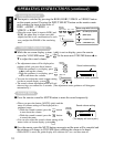
■ Upper left vertical mounting
■ Horizontal mounting
Plasma display outline
Wall
surface
Driving anchor bolts into
a wall surface
Plasma display outline
Anchor bolt
Hold to 25 mm
(1 inch)
or below.
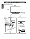
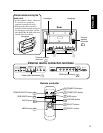
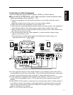
SPEAKER
TERMINAL
8Ω 8W
SPEAKER
TERMINAL
8Ω 8W
SPEAKER
TERMINAL
8Ω 8W
SPEAKER
TERMINAL
8Ω 8W
Horizontal mounting
Upper left vertical mounting
•
The mounted unit should
have the indicating lamp
at its bottom. Otherwise,
an elevated internal
temperature rise could
cause the unit to fail or
fire.
CAUTION