


CHAPTER 4 SETTING
6
Rotary switch
CODE
Dip switch
TYPE
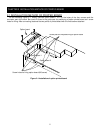
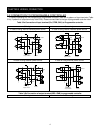
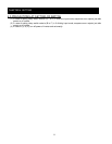
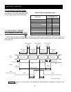
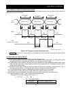
Figure 4-1 Position of switch
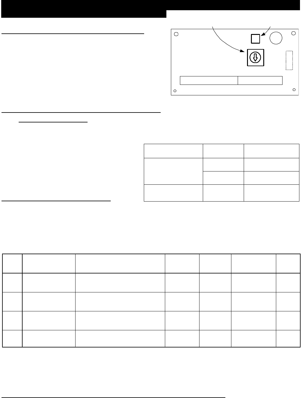
4.1 POSITION OF SETTING SWITCH
Figure 4-1shows position of setting switch.PAC, DIV,
BIN, BCD which printed around the dip switch (TYPE)
means one time input , 2 dividing input, binary input, BCD
input.
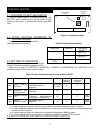
4.2 INITIAL SETTING CONDITION OF
PRINTED BOARD
Table 4-2 shows initial setting condition
(Setting condition at shipment).
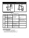
4.3 SETTING OF INVERTER
Table 4-3 shows setting items of the inverter
(SJ300, L300 series) related to operating SJ-DG.
Make sure to refer to “CHAPTER 3 OPERATION”, “CHAPTER 4 EXPLANATION OF FUNCTION” of the
instruction manual of the inverter, and set exactly.
(1) In case of setting frequency, make sure to set frequency command destination (A001) to option.
(2) In case of setting acceleration and deceleration time, make sure to set acceleration and deceleration time 1
selection (P031) to option.
(3) In case of setting torque limit, make sure to set torque limit selection (B040) to option.
(4) In case of setting position, make sure to set selection of position command (P032) to option.
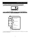
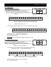
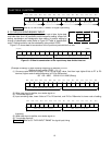
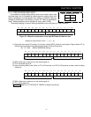
4.4 INPUT MODE BY DIP SWITCH AND ROTARY SWITCH
Table 4-2 Initial setting condition
Setting item Switch No. Initial setting
condition
2 PAC (OFF)
1 BIN (OFF)
Rotary switch
CODE
0 to 0
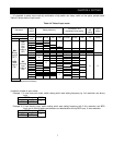
Table 4-3 Table of setting items of inverter related to SJ-DG
Code Function name Data range Initial data Possible
setting at
operating
Possible mode
of change at
operating
Note
A001
Setting frequency
destination
00(VR)/01(terminal)/02(operator)
/03(RS485)/04(option1)
/05(option2)
02 (SJ300)
00 (L300P)
X X -
P031
One selection of
acceleration and
deceleration time
00(remote)/01(option1)
/02(option2)
00 X O -
B040
Selection of torque
limit
00(4quadrant individual setting)
/01(terminal switch)/02(analog
input)/03(option1)/04(option 2)
00 X O
Only
SJ300
P032
Selection of
position command
00(remote)/01(option1)
/02(option2)
00 X O
Only
SJ300