


CHAPTER 5 FUNCTION
10
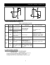
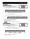
Setting of dip switch TYPE
1 2
BIN DIV
Precaution Refer to 5.3 ”DATA INPUT TIMING” for signal input timing.
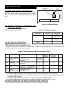
5.1.3 TWO DIVIDING BINARY INPUT
It is possible to change setting data by twice input of data, higher data
and lower data. And it is possible to select frequency setting, torque limit
setting, acceleration and deceleration time setting or position setting by
change of classification code (Refer to Figure 5.2 Table of classification
code.). Setting resolution can be selected by rotary switch CODE.
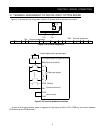
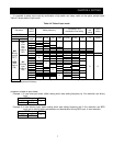
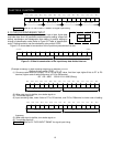
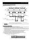
Figure 5.1.3 shows data bit construction of the input binary data divided into two.
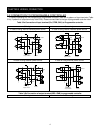
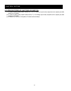
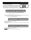
(Example of setting) In case of setting frequency to resolution 0.01Hz
(Setting of rotary switch CODE --- 0, 1, 2
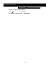
(1) Converse value which 60 multiply 100 to 16 bits binary value. And then input higher 8 bits to D7 to D0
terminal, higher code of setting frequency to D15 to D8 terminal.
60×100 = 6000 0001011101110000 (Binary)
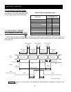
(2) When data input is definite, turn strobe signal on.
(3) Turn strobe signal off.
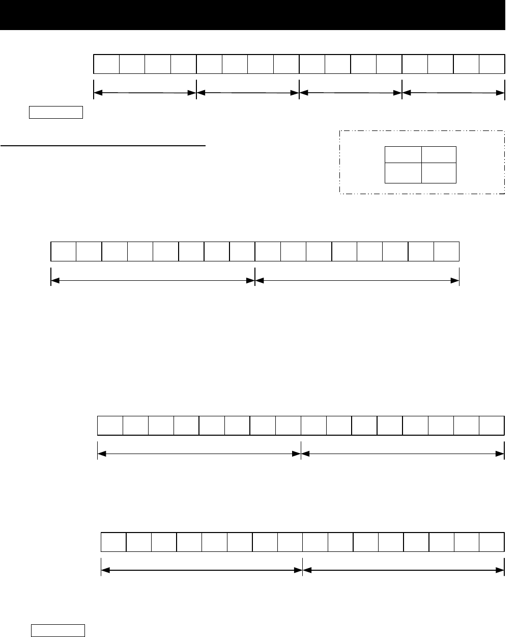
(4) Input remaining data, lower 8 bits to D7 to D0 terminal, and D15 to D8terminal to lower code of setting
frequency.
(5) When data input is definite, turn strobe signal on.
(6) Turn strobe signal off.
Precaution Refer to 5.3 ”DATA INPUT TIMING” for signal input timing.
D11 D10 D 9 D 8 D 7 D 6 D 5 D 4 D 3 D 2 D 1 D 0
(Higher)
(Lower)
Higher or Lower classification code
D15 D14 D13 D12
Setting data of higher 8bits or lower 8 bints
Figure 5.1.3 Data bit construction of the input binary data divided into two
D11 D10 D 9 D 8 D 7 D 6
D 5 D 4 D 3 D 2 D 1 D 0
1 0 0 0 0 0 0 000000100
D12D13D14D15
Setting data 4 Setting data 3 Setting data 2 Setting data 1
Higher code setting frequency
Higher 8 bits setting data
D11 D10 D 9 D 8 D 7 D 6 D 5 D 4 D 3 D 2 D 1 D 0D12D13D14D15
0 0 0 0 0 1 1 101100000
Lower code setting frequency
Lower 8 bits setting data
D11 D10 D 9 D 8 D 7 D 6 D 5 D 4 D 3 D 2 D 1 D 0D12D13D14D15
0 0 1 0 1 0 0 001100000