


272630D Auxiliary Board
INSTALLATION
When installing this product...
1. Read these instructions carefully. Failure to
follow them could damage the product or
cause a hazardous condition.
2. Check ratings given in instructions and on
the product to ensure the product is suitable
for your application.
3. Installer must be a trained, experienced
service technician.
4. After installation in complete, check out
product operation as provided in these
instructions.
!
CAUTION:
1. Disconnect power supply before beginning
installation to prevent electric shock and
equipment damage.
2. All wiring must comply with applicable local
electrical codes, ordinances and regulations.
3. DO NOT electrically operate the ML6-7984
actuator before assembly to the valve
because damage not apparent to the installer
may occur. Mount the actuator to the valve
before connecting to power.
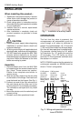
Assembly
1. Remove plastic cover from the ML6-7984
by loosening the two screws located on the
top. (Note: These screws are captive.
Rotate three complete revolutions to
remove cover).
2. Slide the auxiliary board into the two slots
at the bottom of the bridge. Push back and
snap the board into the fingers. (See Fig. 1)
3. Connect one end of the 4-pin connector to
the main board and the other end to the
auxiliary board if it is not already connected.
The connectors are keyed and only install
one way.
4. Mount the actuator onto the valve body and
connect wiring.
5. Reinstall cover after operational check.
Fingers Bridge
Slots
1. Install
circuit
board
Fig. 1 - Installation of auxiliary board
OPERATION
The first time the valve is powered, the
microprocessor will automatically cycle the
valve through a full stoke to calibrate its
position. Any stroke between 1/2" (13 mm) and
1" (25 mm) will be divided into 30 equal steps.
Run time will be proportional to stroke length.
(For example: nominal timing for 3/4" stroke
is 63 seconds. For 1/2" stroke this would be
42 seconds). The LED lights up when
terminals T5-T6 are powered, and flash when
the actuator is in motion.
NOTE: 272630D requires that the actuator be
continuously powered, so ML6984 must be
wired in "5-wire" configuration.
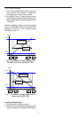
C-NC contact
C-NO contact
CLOSED
CLOSED
2-10 V,
when valve
when valve
(4-20 mA
position is
position is
into
below trim pot
above trim pot
500 Ω)
setting (direct
setting (direct
feedback
acting).
acting).
output COM
Trim pot
J1
LED
+FBNC C NO
RLY1
-COM
Connect to main
board for position
feedback.
Fig. 2 - Wiring and operation of auxiliary
board 272630D
2