


The 272630D provides:
1. A 2-10 Vdc voltage proportional to the valve
stem position. This output is capable of
sourcing up to 20 mA dc drive current.
2. An isolated "Form C" relay contact closure
that energizes when the valve is open more
than the setting of the trimmer potentiometer
("trim pot").
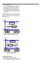
Position feedback voltage mirrors the control
signal. For ML6984 and direct acting ML7984
operation, see Fig. 3. For reverse acting
ML7984, see Fig. 4.
1.75V 2.5V 9.5V 10.25V
FEEDBACK VOLTAGE
LOWER
SEAT
UPPER
SEAT
STROKE
28 steps @
0.25V per step
First and last steps
are @ 0.75V per step
Fig. 3 - Feedback voltage reponse for
ML6984 and direct acting ML7984
STROKE
10.25V9.5V2.5V1.75V
FEEDBACK VOLTAGE
LOWER
SEAT
UPPER
SEAT
28 steps @
0.25V per step
First and last steps
are @ 0.75V per step
Fig. 4 - Feedback voltage response for
reverse acting ML7984
Auxiliary Switch Setup
1. Drive actuator to desired position.
2. Adjust trimmer potentiometer ("trim pot") until
relay is energized. (On-board LED will light).
3