


63-2524 2
43191680-105 AUXILIARY SWITCH
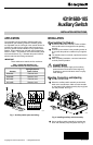
Fig. 3. Securing auxiliary switch assembly.
ᕤ Secure terminal block and terminal label with Phillips
head screws. See Fig. 4 .
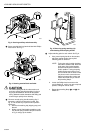
Fig. 4. Securing terminal block and label.
CAUTION
The manual spring handle is under tension and
could turn quickly when lifted resulting in injury to
fingers pinched between the handle and plastic
casing. Maintain handle orientation while lifting and
remove fingers quickly when releasing.
ᕥ Remove manual spring handle retaining clip, if
necessary, and lift and release the handle. See
Fig. 5. The easiest way to perform this operation
safely is to:
a. Remove the retaining clip (shipping stop) and
discard.
b. Wedge a small, flat-bladed screwdriver under
the manual spring handle at the point marked
in Fig. 5 and pry up the handle.
Fig. 5. Removing spring retaining clip
and releasing manual spring handle.
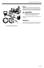
ᕦ Adjust switching point for each switch. See Fig. 6.
a. Using manual spring handle on the actuator,
adjust the actuator shaft to the required
switching point for Switch S1.
NOTE: Turning the spring handle clockwise
extends the actuator shaft. When the
shaft gets to the required position,
press the handle down to hold the
shaft in position. Turning the spring
handle requires two hands, one to
turn the handle and the other to hold
it in place on each consecutive turn.
Observe the preceding caution and
release the handle only as noted in
the preceding Step 5.
b. Loosen the Phillips head set screw on the
cam for Switch S1, set the cam to the required
position, and tighten the set screw.
c. Repeat the preceding Steps ᕦa and ᕦb for
Switch S2.
C8395
S1
S2
C8396
S1
S2
4 MM
3 MM
M6629