


63-2524
3
43191680-105 AUXILIARY SWITCH
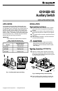
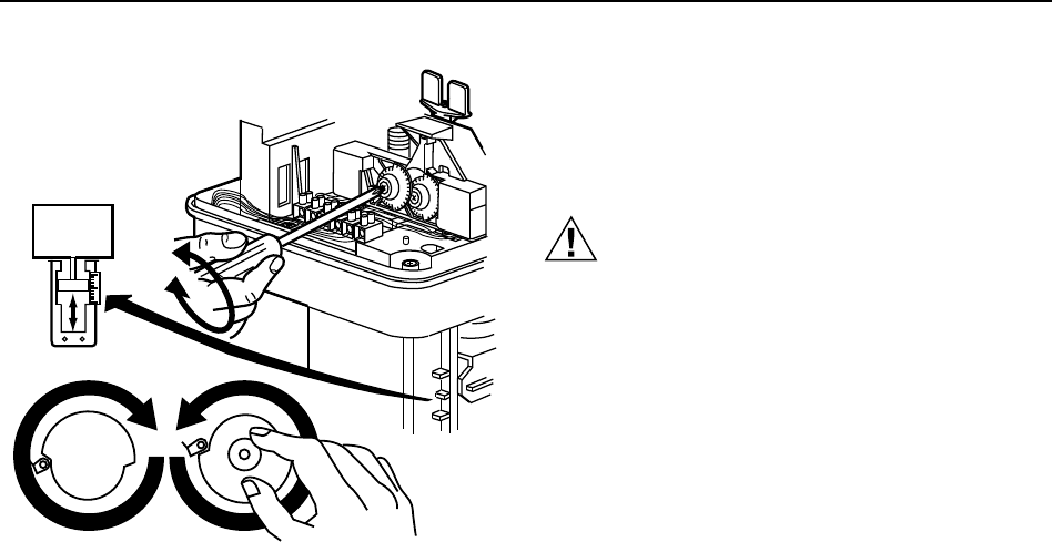
Fig. 6. Adjusting switching points.
C8397
S1
S2
1 X MAX.
100
0
i
i
i
i
i
i
i
i
i
i
i
i
i
i
i
i
i
i
i
i
i
i
i
i
i
i
i
i
i
i
i
i
i
i
i
i
i
i
i
i
i
i
i
i
i
i
i
i
i
i
i
i
i
i
i
i
i
i
i
i
i
i
Wiring
Route field wiring in through the conduit opening in the
bottom of the actuator, connect to the switch assembly
terminal block according to the job drawings, and replace
the actuator cover. See Fig. 1 for terminal identification.
CAUTION
Disconnect the power supply to the auxiliary
switches and actuator before wiring to prevent
electrical shock or equipment damage.
All wiring must comply with local codes, regulations, and
ordinances.
CHECKOUT
Drive actuator shaft fully up and fully down and check the
function of the auxiliary switches in the control system.