


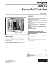


L404F,T,V PRESSURETROL
®
CONTROLLERS
71-2429—2 4
IMPORTANT
When making pipe connections, use pipe dope
sparingly to seal the joints; any excess dope may
clog the small hole in the fitting and prevent the
controller from operating properly.
Location and Mounting (L404F)
Locate the L404F where the ambient temperature will not
exceed 66°C (150°F). The L404F can be mounted near the
pressure gauge, at a remote location, in a fitting provided by
the boiler manufacturer, or in a special mounting on low water
cutoffs. The L404F should always be mounted above the
water line in steam boiler applications.
NOTE: For accurate operation, supplemental heat should be
added to installations where temperatures fall below
-29°C (-20°F).
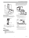
A steam trap must be connected between the L404F and the
boiler (see Fig. 2) to prevent boiler scale and corrosive vapors
from attacking the elbows or diaphragm.
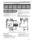
Fig. 2. Steam trap mounting.
Pressure Gauge Mounting
To mount beside a pressure gauge, remove the gauge, and
install in its place the steam trap with a tee on top. Mount the
PressureTrol
®
unit and pressure gauge on the side of the tee
by means of nipples and elbows (see Fig. 2).
Remote Mounting
Excessive vibration at the boiler may affect the operation of
the L404F. In these cases, the L404F should be remotely
located, subject to the following:
1. All piping must be suitable and properly pitched to drain
all condensation back to the boiler.
2. The remote mounting must be solid.
3. A steam trap must be used at one end of the piping.
Boiler Mounting
If it is not convenient to mount the L404F adjacent to the
pressure gauge, install a steam trap at the location
recommended by the boiler manufacturer, then screw the
device directly to the steam trap.
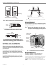
Location and Mounting (L404T,V)
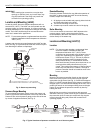
Location
NOTE: For most accurate operation, supplemental heat
should be added to installations where the
temperature falls below -20°F (-29°C).These
controllers can be mounted at any location in the oil
supply line, depending on the application. Typical
locations are shown in Fig. 3. The low oil pressure
controller should be located upstream from the
safety shutoff valve(s). In a downstream location,
there would be zero pressure when the burner is not
running and the safety shutoff valve(s) is (are)
closed. This could prevent startup or require manual
reset every time the burner is started. The high oil
pressure controller should be located as near to the
burner as possible.
Mounting
Mount the oil pressure controller directly on the main pipe.
Insert a tee in the pipe line, and connect a pipe nipple of
appropriate size to the tee (see Fig. 4). Screw the hexagonal
fitting (1/4-18 NPT internal thread) of the pressure controller to
the pipe nipple. To avoid leaks and damage to the case, use a
parallel jaw wrench on the hexagonal fitting close to the pipe
nipple. Do not tighten the pressure controller by hand by
holding the case.
Make all pipe connections in accordance with approved
standards. Use only a small amount of pipe compound to seal
the connection joints. Excess pipe compound may clog the
orifice in the pipe fitting and prevent the controller from
operating properly.
Fig. 3. Typical locations of pressure controllers in an oil burner system.
4-1/2 TO 5-1/2
(114.3 TO 139.7)
BOILER
14026
STEAM TRAP
(SIPHON LOOP)
TEE
PRESSURE
GAUGE
PRESSURE
CONTROLLER
M8934B
1
1
1/4 IN. BLACK IRON PIPE WITH 1/4 - 18 NPT EXTERNAL
THREADS ON BOTH ENDS AND 2-1/4 IN. DIAMETER LOOP.
MAIN
OIL
LINE
TO OIL
BURNER
ATOMIZER
ATOMIZING MEDIUM
(AIR OR STEAM)
MANUAL
SHUTOFF
VALVE
LOW OIL
PRESSURE
CONTROLLER
HIGH OIL
PRESSURE
CONTROLLER
RECIRCULATING
VALVE AND SAFETY
SHUTOFF VALVE
OIL
PUMP WITH
PRESSURE RELIEF
LOW OIL
TEMPERATURE
STRAINER
MANUAL
SHUTOFF
VALVE
M17861