


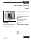


L404F,T,V PRESSURETROL
®
CONTROLLERS
5 71-2429—2
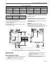
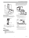
Fig. 4. Mounting an oil pressure controller
directly on the main pipe.
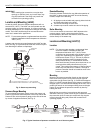
Using with Preheated Oil
When used with preheated oil, a siphon loop (part number
14026) must always be connected between the controller and
the main pipe (see Fig. 5) to provide thermal buffering.
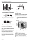
Fig. 5. Mounting of a siphon loop, with approximate
dimensions in in. (mm).
WIRING
WARNING
Electrical Shock Hazard.
Can cause severe injury, death or property
damage.
Disconnect the power supply before beginning wiring.
More than one power supply disconnect may be
required.
All wiring must comply with applicable codes and ordinances.
All models have terminals (on the MicroSwitch
®
snap-acting
switch) inside the cover and knockouts for conduit and cable.
Refer to manufacturer installation and wiring instructions, if
available, and to typical hookups shown in Fig. 6 to 10.
Fig. 6. L404F in low voltage relay circuit.
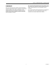
Fig. 7. L404F in a typical 2-wire control circuit.
OIL PRESSURE
CONTROLLER
(AT RIGHT
A
NGLES TO THE
MAIN PIPE LINE)
PIPE
WRENCH
HEXAGONAL
FITTING
MAIN PIPE LINE
M17860
MAIN TEE
(TURN TO LEVEL
THE CONTROLLER)
PIPE NIPPLE
4-1/2
TO
5-1/2
(114 TO
140)
PREHEATED OIL SUPPLY LINE
14026
SIPHON LOOP
TEE
OIL PRESSURE
CONTROLLER
M17858A
1
1
1/4 INCH BLACK IRON PIPE WITH 1/4-18 NPT EXTERNAL THREADS ON
BOTH ENDS AND 2-1/4 IN. (57 MM) DIAMETER LOOP.
M19637
A
1
1
2
2
PROVIDE DISCONNECT MEANS AND OVERLOAD PROTECTION
AS REQUIRED.
AS SHOWN, SWITCH OPENS ON PRESSURE RISE. REVERSE
ACTING (MAKE ON PRESSURE RISE) UNITS ARE WIRED TO
R-W TERMINALS AND TERMINAL B IS OMITTED.
L404F PRESSURETROL
24 VOLT
POWER
SUPPLY
R
W
B
L1
(HOT)
POWER
SUPPLY
24 VOLT RELAY
L2
M19638A
1
1
2
2
PROVIDE DISCONNECT MEANS AND OVERLOAD PROTECTION
AS REQUIRED.
AS SHOWN, SWITCH OPENS ON PRESSURE RISE. REVERSE
ACTING (MAKE ON PRESSURE RISE) UNITS ARE WIRED TO
R-W TERMINALS AND TERMINAL B IS OMITTED.
MOTOR
L404F PRESSURETROL
LINE VOLTAGE
THERMOSTAT
R
W
B
L1
(HOT)
POWER
SUPPLY
L2