


60-2481—2 4
R182J, R482J, R845A, R847A, R882J, RA89A, RA832A
INSTALLATION
MOUNTING
For replacement, mount the relay in the same location as
the old control. If this is a new installation, locate the relay
vertically on a solid wall or partition as near as possible to
the device to be controlled. Select a location that is easily
accessible for installation and service.
NOTE: To reduce possible transformer hum and relay
noise that can be amplified by mounting surfaces of
sheetmetal, plasterboard, and similar materials, place
rubber or felt washers between the case and the mount-
ing surface.
l. Position the relay and mark the mounting holes. See
Fig. 1.
2. Start a screw for the keyhole type mounting hole in
the upper right-hand corner. Turn down screw within about
l/8 in. [3.2 mm] of the surface.
3. Hang the relay on the screw, position the case, and
start the bottom screw.
4. Tighten both screws.
IMPORTANT: The switching relay terminals are ap-
proved for use with copper wires only.
All wiring must comply with all applicable electrical
codes, ordinances, and regulations. Follow any instructions
furnished with the controlled equipment.
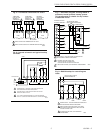
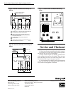
See Figs 2 through 10 for hookup diagrams for these
relays. When two or more devices are to be controlled in
parallel, the total current must not exceed the relay load
rating. Fig. 11 is an internal view of the RA832A, showing
terminal locations and barriers.
Never connect load terminals to a load that takes more
current than the amount listed in the electrical ratings on the
relay. See Table 3 for wiring length specifications.
Fig. 2—Internal schematic and typical hookup
for RA89A.
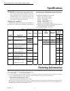
TABLE 3—WIRE LENGTH SPECIFICATIONS.
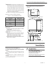
Fig. 3—Internal schematic and typical hookup
for RA832A.
L1
HOT
L2
TT
21 34
1
1
LOAD 2
(OPTIONAL)
LOW VOLTAGE (CLASS 2)
2-WIRE THERMOSTAT
RA832A
POWER SUPPLY. PROVIDE OVERLOAD PROTECTION
AND DISCONNECT MEANS AS REQUIRED.
M3821
LOAD 1
XX
AUXILIARY TO LOW
OR MILLIVOLTAGE
(POWERPILE) LOAD
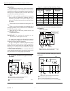
Fig. 4—Internal schematic and typical hookup
for R182J.
AWG Wire
Size
Total Wire
Length
Length of Run to
Thermostat
(2 wires)
(Number)
Feet Metres Feet Metres
22 120 38 60 18
20 200 61 100 30.5
18 300 91.5 1150 45.6
16 500 152.5 250 76
14 800 244 400 122
L1
(HOT)
L2
1
2
1
2
N.O.
N.C.
N.O.
N.C.
WX RB
L1
L2
4
37
6
R182J
K1
K1
K1
K2
K2
POWER SUPPLY. PROVIDE OVERLOAD PROTECTION AND
DISCONNECT MEANS AS REQUIRED.
N.O. CONTACTS MAKE BEFORE N.C CONTACTS BREAK,
AND N.C. CONTACTS MAKE BEFORE N.O. CONTACTS BREAK.
M8232
LOAD
LOAD
3
OHMS
L1
HOT
L2
TT
21 34
1
1
TO LOAD
LOW VOLTAGE (CLASS 2)
2-WIRE THERMOSTAT
RA89A (SPST)
JUMPER
L1
HOT
L2
21 34
1
TO LOAD
RA89A
JUMPER REMOVED
2
CONTROLLER
(IF USED)
1
POWER SUPPLY. PROVIDE OVERLOAD PROTECTION
AND DISCONNECT MEANS AS REQUIRED.
COMPLETE WIRING AS SHOWN ABOVE.
2
M3819