


60-2481—2 6
R182J, R482J, R845A, R847A, R882J, RA89A, RA832A
INSTALLATION • SERVICE AND CHECKOUT
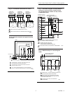
Fig. 9—Internal schematic and hookup for
R847A.
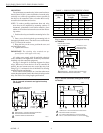
Fig. 11—Internal view of RA832A Switching
Relay.
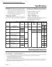
M3824
24V TRANSFORMER
RELAY
12
34
T
T
X
X
L1
(HOT)
L2
TT
L2 L1 34
1
1
TO
POWER
LOW VOLTAGE (CLASS 2)
2-WIRE THERMOSTAT
R847A
POWER SUPPLY. PROVIDE OVERLOAD PROTECTION
AND DISCONNECT MEANS AS REQUIRED.
WHEN CONTROLLING TWO LOADS, USE 3 AND 4
FOR LINE VOLTAGE LOAD AND 5 AND 6 FOR LINE
OR LOW VOLTAGE LOAD.
IF USING LOW VOLTAGE, USE A SEPARATE
TRANSFORMER.
10 AMP CONTACT RATING OR 20 AMP WHEN POLES
ARE CONNECTED IN PARALLEL.
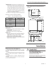
2
M8231B
67
LOAD 1
TO
POWER
LOAD 2
1 1
2
3
44
3
4
Fig. 10—Internal schematic and hookup for
R882J.
3
3
R882J
N.O.
N.C.
N.C.
5
37
6
N.O.
4
2
1
8
M8235
CONTROLLER
LOAD
LOAD
COM. COM.
LOW VOLTAGE
SOURCE
Service and Checkout
1. Never use oil on any part of the relay coil or contacts.
2. Keep the cover on the relay during normal operation
and remove only for service and checkout.
3. Relay contacts require no cleaning; contacts close
with a wiping action and are self-cleaning. They may turn
black after being in service for some time; however, this
discoloration does not prevent proper operation.
4. After installation is complete, operate system through
at least one cycle from the controller to make certain the
relay controls the equipment as intended.
Home and Building Control Home and Building Control Helping You Control Your World
Honeywell Inc. Honeywell Limited—Honeywell Limitée
1985 Douglas Drive North 740 Ellesmere Road
Golden Valley, MN 55422 Scarborough, Ontario
M1P 2V9
Printed in U.S.A.
QUALITY IS KEY