


THE CONTINUOUS POWER COMPANY
Page 7
LOAD
50%
25%
OVER
75%
100%
(800)-44-CLARY WWW.CLARY.COM
STATUS
LOW
BATTERY
FULL
SILENCE/
INV
START
AC IN
OK
ALARM
COLD
LOAD I
LOAD II
ALARM
TEST
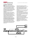
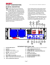
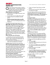
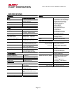
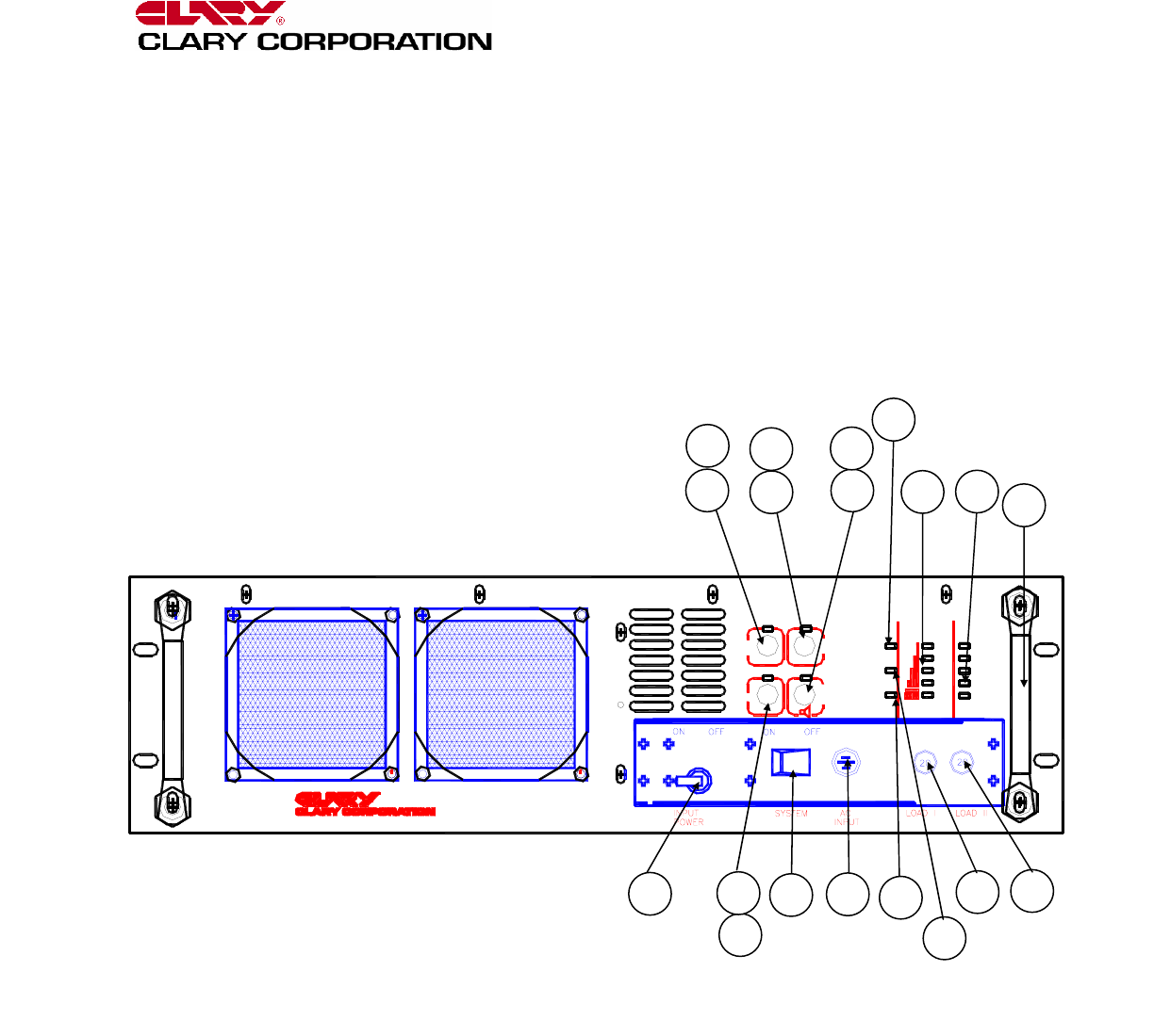
PHYSICAL DESCRIPTION
his section will point out and illustrate the
various indicators, functions and controls of
the CMN SERIES UPS. Pictured is the front
view of the system, then followed by the rear
view. The important attributes of the CMN SERIES
unit is numbered to assist you in locating them on
your machine and also to fully explain its function
and how it relates to system operation.
Numbers on the drawing will correspond to the
operating component’s name at the bottom with a
brief identification. In the next section, a complete
explanation of all numbered items will be enhanced
to ensure you have a full understanding of the
operation of this system.
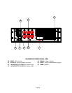
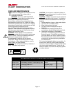
Visual indicators used on the front panel are long
lasting, very efficient, light emitting diodes (LED).
When operating the push-button switches, always
hold the switch in for at least two seconds to insure
function confirmation. This feature has been
implemented into the system design to avoid
inadvertent operation of any of the user-available
functions.
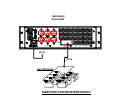
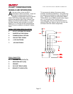
The rear panel has been engineered with the user’s
multiple applications in mind. Two load outputs are
provided with three receptacles per output. The
outputs can be independently switched on or off.
T
RACKMOUNT FRONT PANEL VIEW
1 SYSTEM POWER SWITCH 11 LOAD II - Enable switch for bottom row of output receptacles
2 HANDLES 12 LOAD II ACKNOWLEDGE INDICATOR
3 AC In Ok- Input line indicator 13 ALARM SILENT/TEST - Dual function switch
4 INVERTER - Inverter operating indicator 14 ALARM SILENT/TEST ACKNOWLEDGE INDICATOR
5 BATTERY – Battery level indicators 15 ALARM - Fault indicator
6 LOAD – Load level indicators 16 INPUT CIRCUIT BREAKER
7 COLD START - DC start switch 17 20A CIRCUIT BREAKER FOR LOADI
8 COLD START ACKNOWLEDGE INDICATOR 18 20A CIRCUIT BREAKER FOR LOAD II
9 LOAD I - Enable switch for top row of output receptacles 19 AC INPUT INDICATOR
10 LOAD I ACKNOWLEDGE INDICATOR
2
7
5
6
19
8
12
11
4
14
13
9
10
16
1
15
17
18
3