


THE CONTINUOUS POWER COMPANY
Page 9
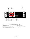
SUMMARY OF INDICATORS AND CONTROLS
SYSTEM POWER SWITCH - The main control
switch that engages utility power to the entire unit.
By activating this switch it initializes normal
operation. Input circuit breaker must be on.
AC In - The utility input indicator that identifies
status of the line voltage. If the line voltage is within
the specified range, it will remain lit. If the AC input
is out of range, this indicator will flash in 1 to 2
second intervals.
Inverter - This indicator identifies the status of the
regenerated, conditioned protected output power.
This indicator will stay ON as long as protected
power is available from the power inverter generator.
Battery Level - This is the battery status bar graph.
During normal operation, this bar graph will show the
charging of the battery; all indicators lit will represent
a fully charged battery. During battery operation,
this bar graph represents a discharge meter
indicating less battery time available as each L.E.D.
turns OFF.
Load Level - This is the system output capacity
status bar. The number of L.E.D.s on the graph
indicate an approximate percentage of system full
load. All lights being ON would indicate full load.
Cold Start - A momentary push-button switch to
activate the system in the event no utility power is
present. The system will be allowed to start up by
using power from its batteries. Turn on the System
Power Switch. Press and hold the Cold Start Switch
until the audible alarm beeps once. Press and hold
the LOAD I or II switch. The system will maintain a
load depending upon the condition of the battery.
Load I and Load II - A momentary push-button
switch that toggles the output LOAD I or II AC output
outlets at the rear panel “ON /OFF”. The indicator
above the switch will be ON to represent that LOAD I
OR II Is activated. The output can be turned OFF by
pressing and holding the switch. While the switch is
depressed, the indicator will blink to represent
transition. Once the indicator stops blinking, the
switch can be released for a successful transition.
Alarm Silent/Test - A momentary push-button
switch that controls two different functions
depending on the mode of operation. In the normal
mode of operation, if this switch is depressed and
held in, the above indicator will blink. Once it stops
blinking, the unit will perform an internal 1 to 2
minute battery check. Once the test is completed, if
the battery is below standards, the system will
indicate that the battery needs replacing. The
system will not run this battery test unless the
battery is detected to be fully charged. During
battery or abnormal operation, an audible alarm will
accompany this mode. By depressing this switch,
the adjacent indicator will blink. When it stops
blinking, the alarm will be silenced. Once the fault or
reason for the alarm is corrected, this audible alarm
condition will automatically reset. The audible alarm
can be re-enabled during abnormal conditions by
pressing and holding the switch again.
NOTE - All switches must be held in for at least two
seconds to engage their function. This is to prevent
any inadvertent switch operation.
Alarm - This is a fault indicator that will light in the
event that the inverter generator is non-operable.
This could be due to an “over-temperature” situation
or an inverter malfunction.
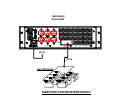
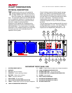
DC INPUT - The battery input connector to add
batteries.
120VAC OUTPUT (Load I & Load II) - The output
groupings that can be independently controlled by
the corresponding front panel switch. During normal
operation, inverter generator power is supplied at
these outlets.
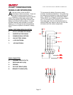
SIGNAL - A DB-9 subminiature, female connector
that outputs the open collector signal contacts for
utility interrupt, low battery and inverter active
conditions.
RS232 - A DB-9 subminiature, female connector that
outputs true RS232 communications signals.
COOLING FAN - The cooling device necessary to
maintain operation without defect. This cooling fan
draws air directly across the internal heatsink.
IDENTIFICATION LABEL - The model number and
serial number of the system is located here. Always
refer to this information when corresponding with the
factory.