


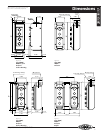

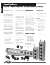
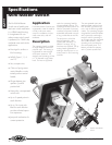
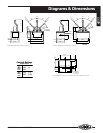

Diagrams & Dimensions
2030
13
440/428-1161 • Fax 440/428-7635
HUBBELL
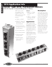
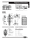
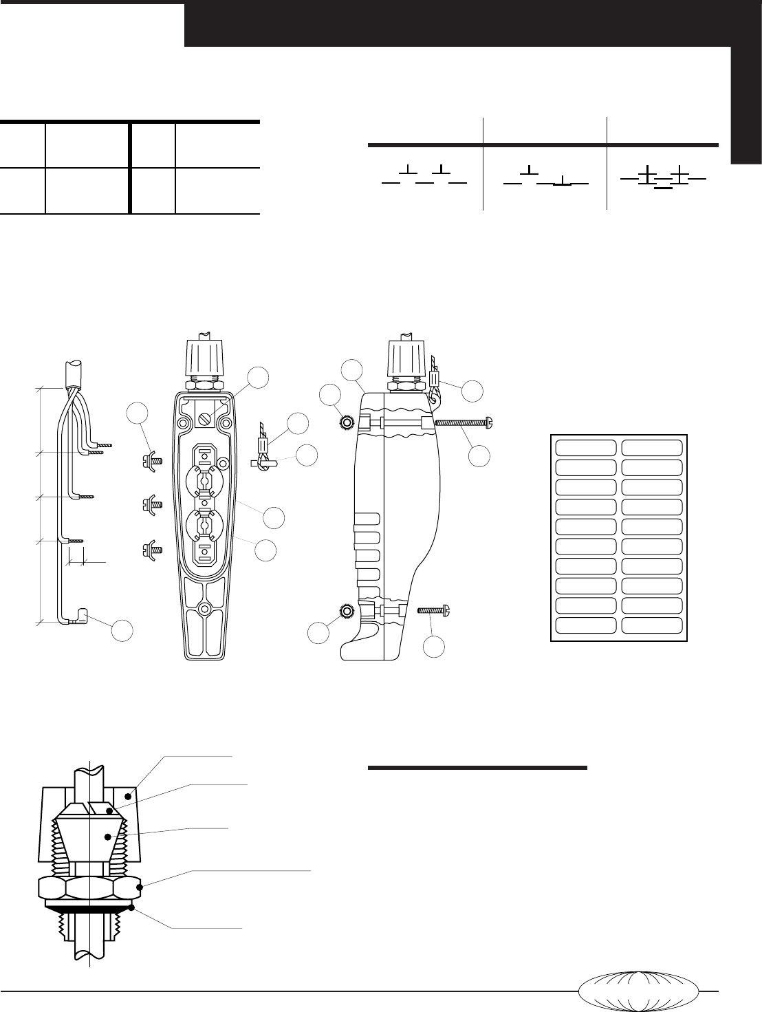
Compact Assembly Parts List
Part
No. Qty. Assembly Parts Listing
1 1 Front Housing
2 1
1
⁄
2
" NPT Locknut Gnd. Brkt.
3 3 Terminal Clamps
4 1 Pin
*
5 1 Crimp Sleeve
*
6 1 Gasket
7 1 Rear Housing
8 3 #8-32 Hex Nut
9 2 #8-32 x 1
3
⁄
4
" Lg. R.H.M.S.
10 1 #8-32 x 1" Lg. R.H.M.S.
11 1 Button Labels
(not shown)
12 190° Terminal
(Two-Speed Only)
*
Discard items no. 4 and 5 if not used as shown.
N/O 1 2nd
Speed
N/O 2
Tab
Bott.
Top
N/O 1 Com. N/O 2
Ctr.
Bott.
Top
N/O 1 Com. N/C 1
Ctr.
Bott.
Top
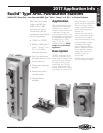
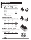
1
⁄
2
" NPT Connector Housing
(Max. Torque 50 In.-Lbs.)
Bushing
(0.37"–0.50" or 0.50"–0.62"
)
Sealing Washer
(UL Listed for hand tightening)
Gotcha Ring
(Blue: 0.37"–0.50" or
Brown: 0.50"–0.62")
Connector Cap
Cord Connector Kit Assembly
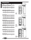
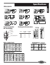
Wiring Diagrams
Single – Speed
†
Momentary (on/off) Two – Speed
†
†
Single-speed and two-speed stations are mechanically interlocked to
prevent actuating both buttons simultaneously.
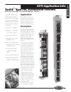
Compact
Pendant
Assembly
6
8
8
9
5
10
12
3
4
5
2
1
Internal Strain
Relief
External Strai
n
Relief
Ground Screw
(green)
Insure gasket is
seated properly.
Crimp
7
Cord Connector Kit
not included.
2.5" 1.5" 1.5" 2.0"
.4"
Cable Stripped Length
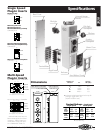
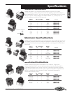
Contact Ratings – Single Break
Single Speed Two Speed
AC
DC
NEMA
A300
NEMA
P300
*
OSHA limits pendant voltage to 150VAC or 300VDC
120V
240V*
6A
3A
125V
250V
1.1A
0.55A
AC
DC
NEMA
B300
120V
240V*
3A
1.5A
125V
250V
—
—
Label Pack
UP
ON
IN
FWD
RIGHT
RAISE
START
OPEN
NORTH
EAST
DOWN
OFF
OUT
REV
LEFT
LOWER
STOP
CLOSE
SOUTH
WEST