


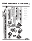
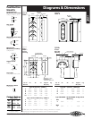
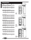
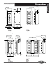

Diagrams & Dimensions
2001
3.625" 2.625"
"B""A"
"P" Pipe
Size
5" 0.375"
8.625"
1.25" Pipe Tap
"A"
3.625" 2.625"
1.062"
2.25"2.25"
0.5"
1.812"
1.375" 1.375"
0.218"ø Mtg.
Hole (4) Internal
1.062" & 1.312"
Concentric
Knockouts Each End
"B"
"A"
3.875" 3.437" 0.5"
"A"
"P" Pipe
Size
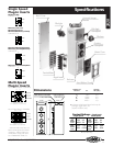
No. of “A” “B” “P” Approx. Fig.
Buttons Wt. (lbs.)
Type HD Pendant – NEMA 1
2 6.31" 0.56" 0.75" 2.00 1
4 10.00" 0.56" 0.75" 3.75 1
6 13.75" 1.63" 1.00" 4.75 1
8 17.37" 2.00" 1.25" 6.00 1
10 21.12" 2.00" 1.25" 7.50 1
Type S Surface Mounting – NEMA 1
2 6.31" 1.81" — 2.00 2
4 10.00" 5.50" — 3.25 2
6 13.75" 9.25" — 4.50 2
8 17.37" 12.87" — 6.00 2
No. of “A” “B” “P” Approx. Fig.
Buttons Wt. (lbs.)
Type WP* Pendant – NEMA 3R
2 5.68" — 0.50" 2.50 3
4 9.19" — 0.75" 4.50 3
6 13.44" — 1.00" 6.50 3
8 17.00" — 1.25" 8.50 3
Type PB4 NEMA 1 & WP4 NEMA 3R Rigid Arm
Mounting
PB4
2 2.62" —— 5.00 4
WP4
2 3.43" —— 5.00 4
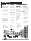
Figure 1
Type HD
NEMA 1
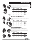
Figure 3
Type WP
NEMA 3R
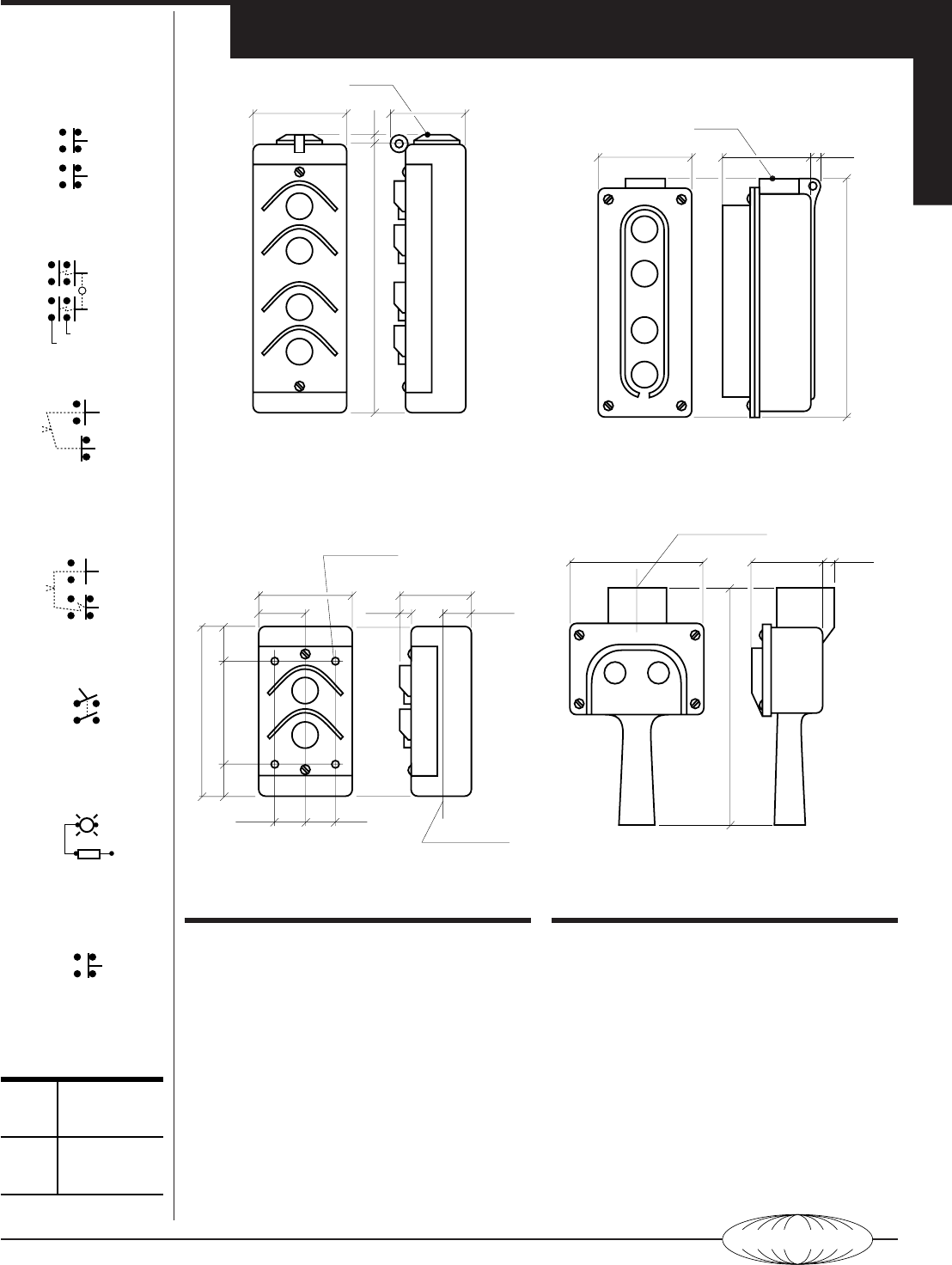
Figure 4
Type PB4
& WP4
Rigid Arm
Mounting
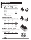
Figure 2
Type S
NEMA 1
Surface
Mounting
*
WP Station also available for surface mounting. Dimensions on request.
All dimensions are approximate and are not for construction purposes.
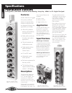
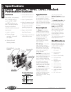
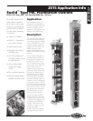
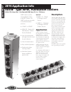
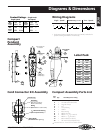
Pushbutton
Inserts
Single Speed or
Momentary Start-Stop
Cat# J1/J1A & K1/K1A
Two Speed
Cat# J2/K2
Maintained Start-Stop
Cat#JM/KM
Maintained/
Momentary Lift/Drop
Cat# JN/KN
Toggle Switch
Cat# JT
Pilot Light
Cat# JP1/JP5 & KP1/KP5
Momentary Reset
Cat# JR/KR
FWD
REV
UP
DOWN
Low Speed
High Speed
START
STOP
LIFT
DROP
Maintained
Momentary
OFF ON
Toggle Switch
R
Pilot Light
Reset
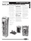
Contact Ratings
Single Break
AC
DC
NEMA
A300
NEMA
P300
*
OSHA limits pendant voltage
to 150VAC or 300VDC
120V
240V*
6A
3A
125V
250V
1.1A
0.55A
3
440/428-1161 • Fax 440/428-7635
HUBBELL