


14A-3
SEPTEMBER 2007HUBBELL / CHANCE COMPANY – CENTRALIA, MISSOURI
®
®
POWER SYSTEMS, INC.
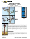
• Automation-ready design
• 900-ampcontinuousand
interruption current rating
• Four-linkovertoggle
mechanism
• Hookstickoperation
capability
• Unitized,pre-assembled
construction
• Fourmountingarrangements
Feature —
Available Options
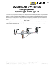
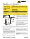
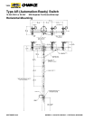
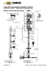
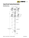
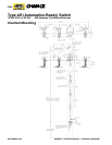
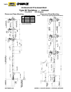
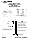
Type AR (Automation-Ready) Switch
14.4kV, 25kV or 34.5kV 900 Amperes Continuous/Interrupt
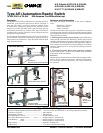
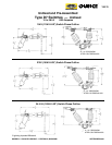
Hook stick Operation The Type AR switch can be operated
by a hook stick operation. This option eliminates control
pipe sections down the pole and their attendant adjustment
during installation and maintenance.
Extra Pipe The extra pipe section includes guide, coupling,
and all hardware for attachment.
Extension Links When deadending to the AR switch, exten-
sion links must be used to give needed clearance. The end
clevis has a slotted hole for inserting the machine bolt with-
out having to remove the extension bar. The extension links
supplied are 14 inches long, hot-dip galvanized, and REA
accepted. Catalog No. C2070112; six required per switch.
Surge Arrester Brackets Three brackets can be supplied
for mounting six surge arresters (utility supplied) for over-
voltage protection.
Sensor Brackets Extension Brackets can be supplied, or
added to the AR Switch, to allow for the additon of line volt-
age/current sensors.
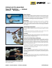
Advantage —
• Compatiblewithtoday’sD/Aenvironmentbyaddingamotoroperator
and RTU of your choice, or upgrade in the future
• Meetspresentandfutureoperationrequirements
• Mechanicaladvantagereducesoperatingtorquetothelowestlevel
in the industry to date
• Overtoggle feature assures blades are closed and gives “snap”
feedback to the operator
• Minimizesinstallationtime,reducespossiblevandalism,eliminates
control adjustments
• Minimizesinstallationtimeandeliminatescontroladjustments
• Meetsvariousutilityinstallationrequirements
Crossarm Braces Crossarm braces may be specied as an
option.
ESP
™
polymer Insulators The distribution insulators, 2.25-
inch bolt circle, are available in a U.S.-manufactured ESP
polymer design. They are light weight, durable, and they offer
long-term performance in every type of environment.
Terminal Connectors Catalog No. ATC1343, fortied cadmi-
um-plated aluminum parallel-groove clamp can be supplied
with switches. Six per switch.
Cable Range:
Minimum No. 2 solid copper [0.258 inch (6.55 mm)] to
maximum 500 kcmil copper [0.811 inch (20.60 mm)].
Control Insulator One 150 kV LIW (Lightining Impulse With-
stand - BIL) polymer insulator in vertical control pipe.
Captive Hardware Two stainless-steel spline bolts pressed
into each terminal pad, nuts and lockwashers included.
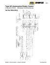
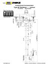
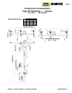
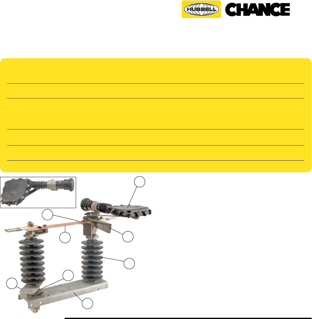
Single Phase of Type AR Switch
(1) Hot-rolled steel base formed into a channel and galvanized
per ASTM A153.
(2) Hot-rolled crank lever provides high strength and corro-
sion resistance. Galvanized per ASTM A153.
(3) Delrin
®
bushing coupled with a cast aluminum rotating
shaft eliminates the need for lubrication during the life of
the switch.
(4) Insulators available in 2.25" bolt circle, porcelain or
polymer.
(5) High-conductivity copper with phosphorous-bronze back-
up springs and copper-tungsten fault-closing tips provide reli-
able contact areas. Silver-to-silver current-transfer points.
(6) Blade formed from hard-drawn, high-conductivity copper
for maximum current carrying capability.
(7) Interrupter provides current interruption without exter-
nal arc or ame. High-strength polyurethane material for
strength, weatherability and UV resistance. Bolted tongue-
in-groove mounting ensures positive alignment.
(8) Polycarbonate ice shield helps protect contacts from ice
build up.
7
1
2
8
4
6
3
Interrupter
5