


NOTE: Use caution while sliding the transducer connectors into the Transducer Switch connectors. The slots for the
c
onnectors are keyed to prevent reversed installation, so do not force the connectors together. See your control head
installation guide for additional information.
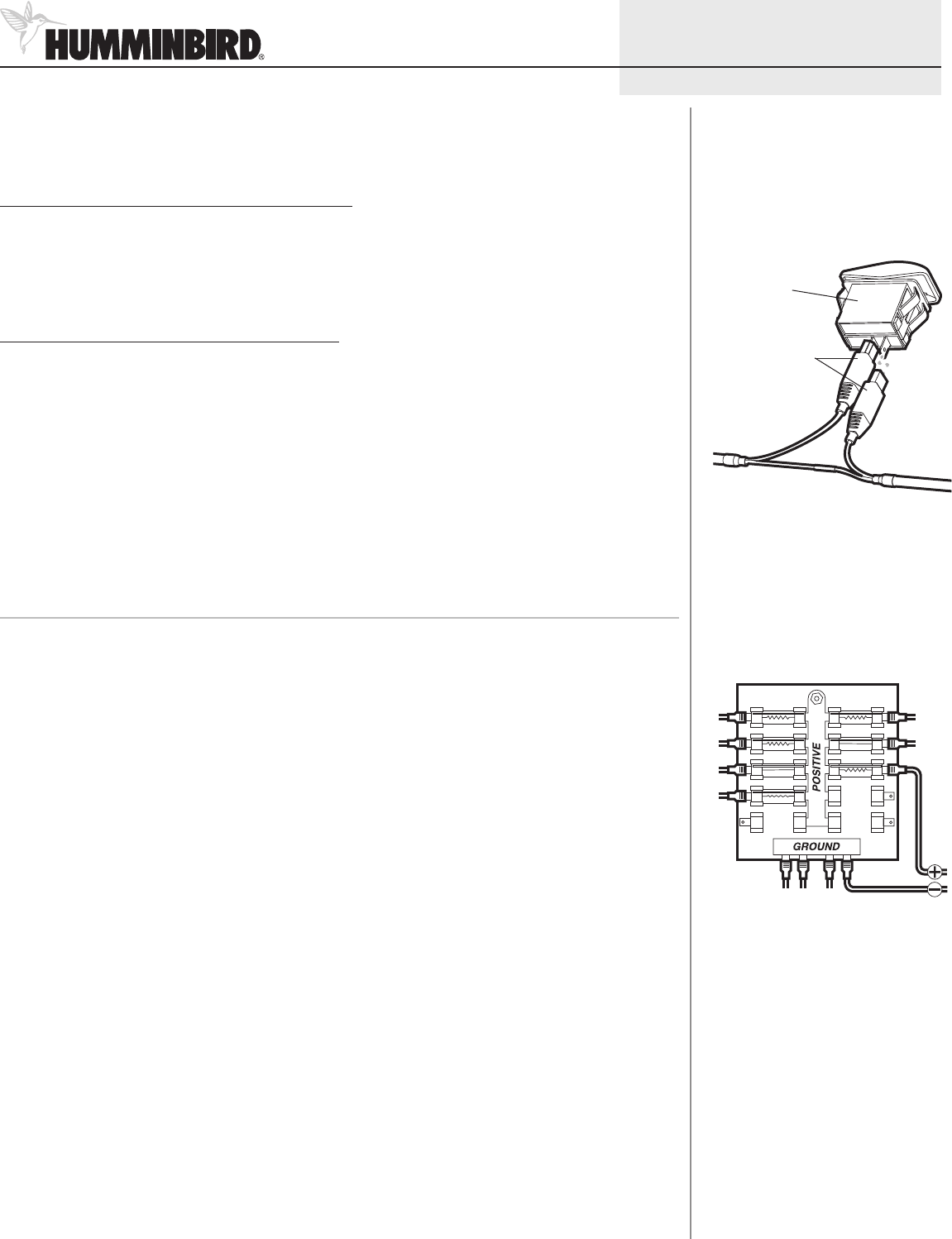
To connect the connector clips to the Transducer Switch:
1. From the back side of the panel, plug the two connector clips from the switch assembly into the two outlets of
the Transducer Switch.
NOTE: Connecting the connector clips to the Transducer Switch does not require a specific order; either connector will work
with either outlet.
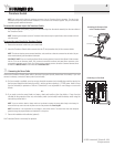
To connect the control head to the Transducer Switch:
1. Remove the connector holder from your control head.
2. Insert the Transducer Switch cable connector into the T2 slot (transducer slot) of the connector holder.
NOTE: The slots are keyed to prevent reversed installation, so be careful not to force the connector into the holder. See your
control head installation guide for additional information.
700 SERIES™ NOTE: If you are installing the Speed Sensor accessory (optional), insert the Sonar/Speed Y-Cable connector
into the T2 slot on the connector holder. Then, connect the transducer connector and speed sensor connector to the
corresponding connectors on the Y-Cable. The Y-Cable requires a separate purchase. Contact our Customer Resource Center
for details at 1-800-633-1468 or visit our Web site at humminbird.com.
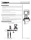
3. Connecting the Power Cable
Connect the Transducer Switch power cable to the boat’s fuse panel (usually located near the console). If you must
connect to a battery, connect to a battery switch (not included).
1a. If a fuse terminal is available, use crimp-on type electrical connectors (not included) that match the terminal on
the fuse panel. Attach the black wire to ground (-), and the red wire to positive (+) 12 VDC power. Install a 3 amp
fuse (not included) for protection of the unit. Humminbird® is not responsible for over-voltage or over-current
failures.
or...
1b. If you need to wire the control head to a battery, obtain and install an inline fuse holder, a 3 amp fuse (not
included) for the protection of the unit, and a battery switch (not included). Install the battery switch using the
instructions provided with it.
NOTE: If you are unable to obtain a battery switch and are forced to connect the power cable directly to the battery, be
aware that this may cause a slow loss of power over time. See procedure five, Powering Off.
NOTE: Humminbird® is not responsible for over-voltage or over-current failures. The control head must have adequate
protection through the proper selection and installation of a 3 amp fuse.
2. Secure the installation with cable ties (optional).
Your Transducer Switch is now ready for operation.
Transducer Switch
3
© 2011 Humminbird®, Eufaula AL, USA.
All rights reserved.
Connecting to a Fuse Panel
531870-1_A
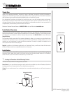
Connecting the Connector Clips
to the Transducer Switch
Connector Clips
Switch