8 RS/6000 7044 Model 170 Technical Overview
Memory Boot Time Deconfiguration
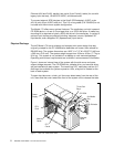
Memory boot time deconfiguration is a function implemented in the service
processor firmware to remove a memory segment or DIMM from the system
configuration at boot time. The objective is to minimize system failures or data
integrity exposure due to faulty memory hardware.
The memory segment or DIMMs that are deconfigured remain offline for
subsequent reboots until the faulty memory hardware is replaced. This requires
powering off the system. Then, this function gives the user the option to manually
deconfigure or re-enable a previously deconfigured memory segment/DIMM
using the service processor menus.
Memory can also be decreased through AIX using the
rmss command. This is
useful for certain benchmark simulations.
System Buses
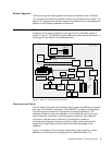
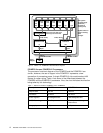
The system bus is controlled by a highly specialized set of custom chips. One
handles addressing and synchronization, the other moves data to and from the
processor (the 6XX bus), memory (memory bus), and the I/O (I/O bus). The 6XX
bus is a 128-bit bus running at a clock speed of either 100 MHz, a 4:1 ratio, when
featured with a 400 MHz processor (which results in a peak data throughput of
1600 MB per second) or 95.1 MHz, a 7:2 ratio, when featured with a 333 MHz
processor.
The 6XX bus is optimized for high-performance and multiprocessing
performance. The bus is fully parity checked and each memory request is range
checked and positively acknowledged for error detection. Any error will cause a
machine check condition and is logged in the AIX error log.
The 6XX and memory buses operate at the same speed, 128-bit width, and have
the same throughput. Their speed is automatically determined by the speed of
the processor installed. Data and address buses operate independently in true
split transaction mode and are pipelined so that new requests may be issued
before previous requests are completed.
PCI Bus, Slots, and Adapters
The Model 170 is compliant with Revision 2.1 of the peripheral component
interconnect (PCI) specifications and implements dual PCI bridge chips in a peer
configuration. One PCI bridge chip provides a 32-bit interface operating at 33
MHz for four PCI slots and the other PCI bridge chip implements a 64-bit bus
operating at 50 MHz for two PCI slots. Slots one and two are 64-bit, 50 MHz, 3.3v
slots and slots three, four, five, and six are 32-bit, 33 MHz, 5.0v slots. All slots in
the Model 170 accept full-sized PCI adapters. The 64-bit slots are physically
keyed to accept either universal or 3.3v cards only. 5.0v cards will not seat in the
card slots. Detailed information is available in the announcement information for
this system.
Memory cards should be physically removed only when the power is turned off
to the entire system.
Note


