


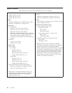
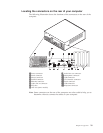
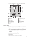
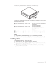
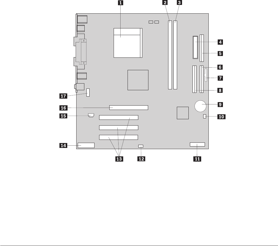
The following illustration shows the locations of parts on the system board.
1 Microprocessor 10Clear CMOS/Recovery jumper
2 DIMM connector 1 11POV card (some models)
3 DIMM connector 2 12SCSI LED connector
4 Power connector 13PCI slots
5 Diskette drive connector 14Front panel audio connector
6 Primary IDE connector 15CD-ROM audio connector
7 Front panel connector 16AGP slot (some models)
8 Secondary IDE connector 17Serial connector
9 Battery
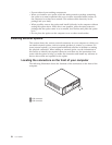
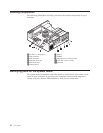
Installing memory
Your computer has two connectors for installing dual inline memory modules
(DIMMs) that provide up to a maximum of 2.0 GB of system memory.
When installing DIMMs, the following rules apply:
v Fill each system memory connector sequentially, starting at DIMM connector 1.
v Use 2.5 V, 184-pin, 266 MHz double data rate synchronous dynamic random
access memory (DDR SDRAM).
v Use 128 MB, 256 MB, 512 MB or 1.0 GB (when available) DIMMs in any
combination.
v DIMMs are 38.1 mm (1.5 inches) in height.
Note: Only DDR SDRAM DIMMs can be used.
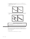
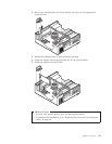
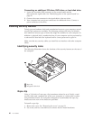
To install a DIMM:
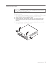
1. Remove the cover. See “Removing the cover” on page 31.
Chapter 2. Type 8191 33