


3301690 CPU Card
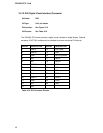
PIN DESCRIPTION DESCRIPTION
1 KB Data 2 N/C
3 GND 4 +5V
5 Clock 6 N/C
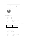
Table 3-17: PS/2 Pinouts
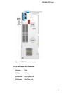
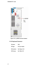
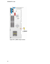
Figure 3-19: PS/2 Pin-out locations
3.3.2 USB Connector
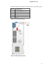
CN Label: USB
CN Type: USB port
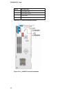
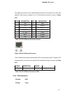
CN Location: See Figure 3-18 (labeled number 2)
CN Pinouts: See Table 3-18
USB devices can be connected directly to the USB connectors on the rear panel.
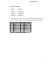
PIN DESCRIPTION PIN
1 +5V 2 DATA-
3 DATA+ 4 GND
Table 3-18: USB Connectors
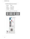
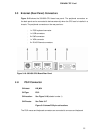
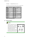
3.3.3 Ethernet Connector
CN Label: LAN1, LAN2
CN Type: RJ-45
CN Location: See Figure 3-18 (labeled number 5)
CN Pinouts: See Table 3-19
56