


3301690 CPU Card
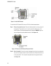
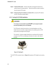
4.3.3.4 DIMM Module Installation
The 3301690 CPU Board has two DDRII SDRAM DIMM sockets. To install the DIMM
modules, follow the instructions below.
Step 1: Pull the two white handles on either side of the DIMM socket down.
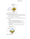
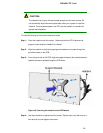
Step 2: Align the DIMM module with the DIMM socket making sure the matching pins are
correctly aligned.
Step 3: Insert the DIMM module slowly. Once you are sure it is correctly inserted, push
down firmly. The white handles on either side of the socket will move back up and
lock the module into the socket. Step 0:
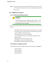
4.3.4 Peripheral Device Connection
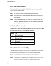
Cables provided by GAI that connect peripheral devices to the CPU Card are listed in Table
4-2. Cables not included in the kit must be separately purchased.
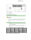
Quantity pe
1 ATA 66/100 flat cable
2 SATA cables
1 SATA power cable
1 Keyboard/ PS2 mouse Y cable
1 RS-232 cable
1 USB cable
Table 4-2: Provided Cables
4.3.4.1 IDE Disk Drive Connector (IDE1)
The cable used to connect the CPU card to the IDE HDD is a standard 44-pin ATA 66/100
flat cable. To connect an IDE HDD to the CPU Card, follow the instructions below.
Step 1: Find the ATA 66/100 flat cable in the kit that came with the CPU Card.
Step 2: Connect one end of the cable to the IDE1 connector on the CPU card. A keyed
pin on the IDE connectors prevents it from being connected incorrectly.
72