


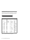
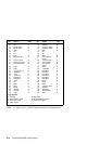
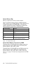

System Memory Map
Memory is mapped by the memory controller registers.
Figure 2-10 shows the memory map for a correctly functioning
system. Memory can be mapped differently if POST detects an error
in system board memory or RT/CMOS RAM. In the figure, the
variable
x
represents the number of 1MB blocks of system board
memory starting at or above the hex 100000 boundary.
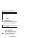
Figure 2-10. System Memory Map
Hex Address Range Function
00000000 to 0009FFFF 640KB system board RAM
000A0000 to 000BFFFF Video RAM
000C0000 to 000C7FFF System board video BIOS ROM mapped to
RAM
000C8000 to 000EFFFF Channel ROM
000F0000 to 000FFFFF 64KB system board ROM mapped to RAM
00100000 to (00100000 +
x
MB)
x
MB system board RAM
FFFF0000 to FFFFFFFF 64KB system board ROM
(same as 000F0000 to 000FFFFF)
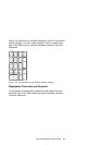
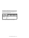
System Board Memory Connector for DIMM
The system board of ThinkPad 560 has one DIMM connector that
directly accepts one 144-pin DIMM of one of the following three
different capacities: 8MB, 16MB, or 32MB.
The system board of ThinkPad 560E has one DIMM connector that
directly accepts one 144-pin DIMM of one of the following four
different capacities: 8MB, 16MB, 32MB, or 64MB (2-bank type).
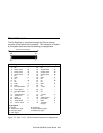
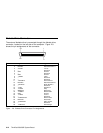
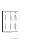
Figure 2-11 on page 2-15 shows the pin assignments for the DIMM
connector.
2-14 ThinkPad 560/560E System Board