


IBM Ethernet Switch B24X 19
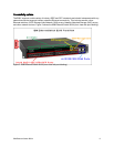
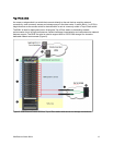
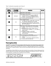
The airflow of the switch is primarily port/side (front) to non-port (back) side. Air is drawn into the system
from vents on the front and front sides of the switch and expelled out the rear. The cooling characteristics
of the system allow it to be deployed in server racks featuring hot-cold aisle containment without the need
of special baffling.
Figure 10. IBM Ethernet Switch B24X airflow
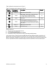
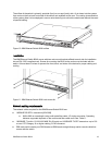
Installation
The IBM Ethernet Switch B24X comes with two rack-mount brackets affixed to each side for installation
into an EIA-310D compliant rack. Screws for mounting the B24X to the rack are not included with the
switch. Allow at least 3 inches of space at the front, back, and sides of the device for proper cabling and
cooling
Figure 11. IBM Ethernet Switch B24X rack mount kit
Network cabling requirements
The network cables required for the IBM Ethernet Switch B24X are:
10GBASE-SR SFP+ transceiver [69Y0389]
z
840 to 860 nm wavelength using multi-mode fiber cable, LC duplex connector. Operating
z
distance supported depends on the multi-mode fiber cable used. See Table 11.
1000BASE-T (built-in 10/100/1000 MbE RJ-45 ports) and 1000BASE-TX SFP transceiver: up to 100
z
m over UTP Category 5e or higher cabling, RJ-45 connector.
DB9 male serial console port: DB9 female-to-DB9 female straight-through serial console cable that
z
comes with the switch.