


Chapter 2 Installation 31
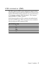
Audio connector (CN13)
The PCM-6890B provides all major audio signals on a 14-pin flat-
cable connector, CN13.
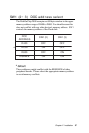
Attach the Mic In, Line In, and Audio Out to the corresponding
pins as shown in the following table.
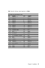
Audio connector (CN13)
Pin Signal Pin Signal
1 Mic In 2 MIC_Vcc
3 GND 4 Reserve for future use
5 Line In Left 6 Reserve for future use
7 Line In Right 8 Reserve for future use
9 GND 10 Reserve for future use
11 Audio Out Left 12 Audio Out Right
13 GND_Line out 14 GND_Speaker out
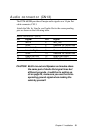
CAUTION: Both Line-out and Speaker-out modes share
the same pair of Audio Out signal lines but
different grounds. In addition to setting up
J5 on page 20, make sure you use the corre-
sponding ground signal when making the
cable by yourself.