


87
CHAPTER 6 8-BIT TIMER/EVENT COUNTERS 5 AND 6
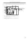
(3) 8-bit timer mode control register 5 (TMC5)
This register enables/stops operation of 8-bit timer register 5, sets the operating mode of 8-bit timer register
5 and controls operation of 8-bit timer/event counter 5 output control circuit.
It sets R-S type flip-flop (timer output F/F 1,2) setting/resetting, the active level in PWM mode, inversion
enabling/disabling in modes other than PWM mode and 8-bit timer/event counter 5 timer output enabling/
disabling.
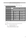
TMC5 is set with a 1-bit or 8-bit memory manipulation instruction.
RESET input sets TMC5 to 00H.
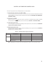
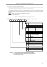
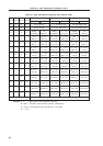
Figure 6-5. 8-Bit Timer Mode Control Register 5 Format
Cautions 1. Timer operation must be stopped before setting TMC5.
2. If LVS5 and LVR5 are read after data are set, they will be 0.
3. Set 0 to the bits 4 and 5.
TCE5
TMC56
0 0 LVS5 LVR5
TMC51
TOE5
76543210Symbol
TMC5
FF53H 00H R/W
Address After Reset R/W
TOE5 8-Bit Timer/Event Counter 5 Output Control
0 Output disabled (Port mode)
1 Output enabled
TMC51
0 Active high
1 Active low
In PWM Mode In Other Modes
Active level selection Timer output F/F1 control
Inversion operation disabled
Inversion operation enabled
LVS5 LVR5
00
01
10
11
8-Bit Timer/Event Counter 5 Timer
Output F/F1 Status Setting
No change
Timer output F/F1 reset (0)
Timer output F/F1 set (1)
Setting prohibited
TMC56 8-Bit Timer/Event Counter 5 Operating Mode Selection
0 Clear & start mode on match of TM5 and CR50
1 PWM mode (free-running)
TCE5 8-Bit Timer Register 5 Operation Control
0 Operation stop (TM5 clear to 0)
1 Operation enable