


60
CHAPTER 4 PORT FUNCTIONS
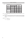
4.2.5 Port 7
This is a 3-bit input/output port with output latches. Input mode/output mode can be specified bit-wise by means
of port mode register 7 (PM7). When pins P70 to P72 are used as input port pins, an on-chip pull-up resistor can
be used as a 3-bit unit by means of pull-up resistor option register L (PUOL).
Dual-functions include serial interface channel 2 data input/output and clock input/output.
RESET input sets the input mode.
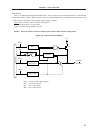
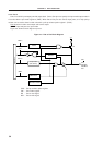
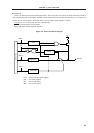
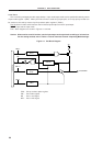
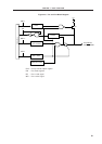
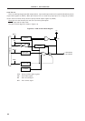
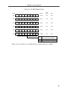
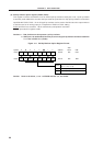
Port 7 block diagrams are shown in Figures 4-7 and 4-8.
Caution When used as a serial interface, set the input/output and output latch according to its functions.
For the setting method, refer to Table 11-2 Serial Interface Channel 2 Operating Mode Settings.
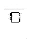
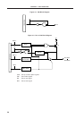
Figure 4-7. P70 Block Diagram
PUO : Pull-up resistor option register
PM : Port mode register
RD : Port 7 read signal
WR : Port 7 write signal
P-ch
WRPM
WRPORT
RD
WR
PUO
VDD
Selector
PUO7
Output Latch
(P70)
PM70
Internal bus
P70/SI2/RxD