


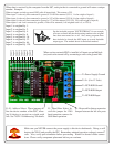
J6
Inputs D0-D7 are pulled up via RN2 4.7K resistor network.
Data Inputs
RS-232
Ground
RS-232
Input
Open Collector
RS-232 Output
J4
J3
J2
J1
+5
J5
CR
1
2
3
CR1
RN1
RN1
+5
V+ +5
78L05
V+
C1C1
D0
D1
D2
D3
D4
D5
A
B
C
G
W
Y
D6
D7
74LS251
4
3
2
1
15
14
11
10
9
7
6
5
13
12
U4
U1
U2
R2
R3
D1
Q1
R4 R5
+5 +5
R1
Q2
Q1
Q0
DatIn
STROBE
ASCII-OUT
AD0
AD1
AD2
AD3
RS-232
BAUD
[110C]
8
7
6
9
18
1
10
11
12
13
2
1715
16
Care should be taken when interfacing to the inputs of this device. Remember, inputs are pulled
high and are activated when they are connected to ground.
Debugging:
Basic checks: Verify all chips are located and oriented in the proper location. Also, check to make sure all pins
are in the socket. Verify all parts are installed according to the directions and that you have a modem cable
attached. Also verify there are no shorted solder connections on the 8SC board. We will also assume the 8SC
board is oriented in the direction shown on the previous page.
Problem: Data is Not (or is Incorrectly) Received by the Computer:
Try: Make sure jumper J6 is installed between the left two posts.
Make sure RS-232 lines are not reversed.
Make sure jumpers J1-J4 are set for the same address set in software. See "NCD-110C Addressing" for details.
Make sure baud rate (J5) matches baud rate in your software.
Make sure the correct "COM" port is used in software.
Make sure the RSB is properly connected and powered.
Make sure resistor R1 is properly installed.
Make sure diode D1 is properly installed.
Make sure Q1 is properly installed.
Make sure 78L05 is properly installed.