


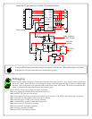

The NCD-110C Interface Processor and How It Works:
The NCD-110C is a PIC-based computer that has been programmed to listen to incoming data on the serial port and to respond ONLY if
its name is called. To understand how it works, we will examine the processes of the 110C as they were written into the chip.
The NCD-110C carefully listens to incoming data on an RS-232 serial port. It breaks each byte that is received into two 4-bit sections.
The first 4-bit section is interpreted as the “Address” of the NCD-110C; the last 4-bit section is interpreted as the mode that is to be used
for obtaining data.
For example, if we send the character 241 to the NCD-110C, the NCD-110C will first convert the character into its binary equivalent of
11110001. Next, it will read the settings of jumpers located on pins 10 to 13. If the jumpers on the NCD-110C are set to 1111 (+5 volts
for all address pins), the mode will be interpreted as 0001. This will cause the 8SC to scan pin 2 of the inputs. (The decimal equivalent
of 0001 is 1, referring to input pin 2.)
The user may select up to nine different modes of operation. Modes 0 to 7 allow the user to grab the status of an individual pin. Mode 8
allows the user to grab the status of all eight pins. Refer to the program below to understand how modes and device number can provide
the user with additional flexibility. This is a partial program example--reference the floppy disk for functional programs.
DEVICE=4 :REM Set the device number. Valid ranges are from 0 to 15.
MODE=8 :REM 15 valid modes.
REM 0-7 grabs status of individual pins.
REM 8-15 grabs status for all pins.
DEV=DEVICE*16 :REM Compute the device number.
PRINT #1, CHR$(DEV+MODE); :REM Send a request to SC8.
PRINT ASC(INPUT$(1, 1)) :REM Read and display the reply from the 8SC.
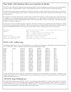
NCD-110C Addressing:
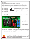
Addressing the NCD-110C is very easy. On all NCD devices, we use jumpers to set the address. These jumpers are always located at pins
10 to 13 on the PIC. We have compiled a table that indicates the possible jumper settings:
Binary Address J1/Pin 10 J2/Pin 11 J3/Pin 12 J4/Pin 13 Range
0000 0 Removed Removed Removed Removed 0-15
0001 1 Installed Removed Removed Removed 16-31
0010 2 Removed Installed Removed Removed 32-47
0011 3 Installed Installed Removed Removed 48-63
0100 4 Removed Removed Installed Removed 64-79
0101 5 Installed Removed Installed Removed 80-95
0110 6 Removed Installed Installed Removed 96-111
0111 7 Installed Installed Installed Removed 112-127
1000 8 Removed Removed Removed Installed 128-143
1001 9 Installed Removed Removed Installed 144-159
1010 10 Removed Installed Removed Installed 160-175
1011 11 Installed Installed Removed Installed 176-191
1100 12 Removed Removed Installed Installed 192-207
1101 13 Installed Removed Installed Installed 208-223
1110 14 Removed Installed Installed Installed 224-239
1111 15 Installed Installed Installed Installed 240-255
Note the Range column--this is a quick way to determine what characters will cause the NCD-110 to respond. For example, on the
second row the range is 16 to 31. When the jumpers are set as indicated by the second row in the table, the NCD-110 will respond to
CHR$() commands from 16 to 31.
74LS251 Input Multiplexer
The NCD-110C is interfaced to the 74LS251. The 251 is a general purpose input multiplexer. It requires 3 bits of data to tell it which of
the eight inputs to look at. The 110C handles pointing operations, minimizing user programming. When a mode 0 to 7 command is
received, the NCD-110C points to the desired input. When a mode 8 to 15 command is received, the 110C scans all eight inputs and
transmits a byte representative of the current input status of all eight inputs.