


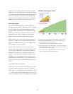
The System z10 EC is designed to provide balanced
system performance. From processor storage to the
system’s I/O and network channels, end-to-end bandwidth
is provided and designed to deliver data where and when
it is needed.
The processor subsystem is comprised of one to four
books connected via a point-to-point SMP network. The
change to a point-to-point connectivity eliminates the need
for the jumper book, as had been used on the System z9
and z990 systems. The z10 EC design provides growth
paths up to a 64 engine system where each of the 64
PUs has full access to all system resources, specifi cally
memory and I/O.
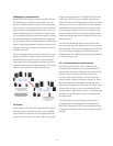
Each book is comprised of a Multi-Chip Module (MCM),
memory cards and I/O fanout cards. The MCMs, which
measure approximately 96 x 96 millimeters, contain the
Processor Unit (PU) chips, the “SCD” and “SCC” chips of
z990 and z9 have been replaced by a single “SC” chip
which includes both the L2 cache and the SMP fabric
(“storage controller”) functions. There are two SC chips
on each MCM, each of which is connected to all fi ve CP
chips on that MCM. The MCM contain 103 glass ceramic
layers to provide interconnection between the chips and
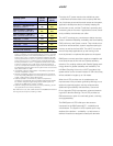
the off-module environment. Four models (E12, E26, E40
and E56) have 17 PUs per book, and the high capacity
z10 EC Model E64 has one 17 PU book and three 20 PU
books. Each PU measures 21.973 mm x 21.1658 mm and
has an L1 cache divided into a 64 KB cache for instruc-
tions and a 128 KB cache for data. Each PU also has an
L1.5 cache. This cache is 3 MB in size. Each L1 cache
has a Translation Look-aside Buffer (TLB) of 512 entries
associated with it. The PU, which uses a high-frequency
z/Architecture microprocessor core, is built on CMOS 11S
chip technology and has a cycle time of approximately
0.23 nanoseconds.
The design of the MCM technology on the z10 EC pro-
vides the fl exibility to confi gure the PUs for different uses;
there are two spares and up to 11 System Assist Proces-
sors (SAPs) standard per system. The remaining inactive
PUs on each installed MCM are available to be charac-
terized as either CPs, ICF processors for Coupling Facil-
ity applications, or IFLs for Linux applications and z/VM
hosting Linux as a guest, System z10 Application Assist
Processors (zAAPs), System z10 Integrated Information
Processors (zIIPs) or as optional SAPs and provide you
with tremendous fl exibility in establishing the best system
for running applications. Each model of the z10 EC must
always be ordered with at least one CP, IFL or ICF.
Each book can support from the 16 GB minimum memory,
up to 384 GB and up to 1.5 TB per system. 16 GB of
the total memory is delivered and reserved for the fi xed
Hardware Systems Area (HSA). There are up to 48 IFB
links per system at 6 GBps each.
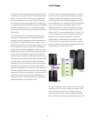
The z10 EC supports a combination of Memory Bus
Adapter (MBA) and Host Channel Adapter (HCA) fanout
cards. New MBA fanout cards are used exclusively for
ICB-4. New ICB-4 cables are needed for z10 EC and are
only available on models E12, E26, E40 and E56. The E64
model may not have ICBs. The Infi niBand Multiplexer (IFB-
MP) card replaces the Self-Timed Interconnect Multiplexer
(STI-MP) card. There are two types of HCA fanout cards:
HCA2-C is copper and is always used to connect to I/O
(IFB-MP card) and the HCA2-O which is optical and used
for customer Infi niBand coupling.
Data transfers are direct between books via the level 2
cache chip in each MCM. Level 2 Cache is shared by all
PU chips on the MCM. PR/SM provides the ability to con-
fi gure and operate as many as 60 Logical Partitions which
may be assigned processors, memory and I/O resources
from any of the available books.
z10 EC Design and Technology
14