


i-7531 CAN Repeater Quick Start User Guide (ver. 1.3, 2008/03/25) -----2
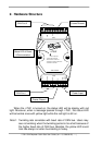
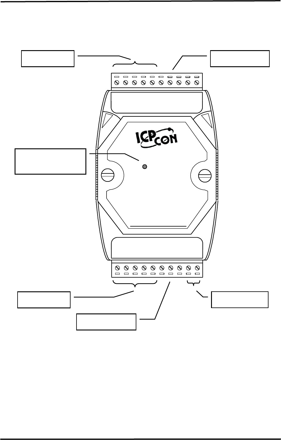
2. Hardware Structure
When the i-7531 is turned on, the status LED will be display with red
light. Moreover, when a message passes through i-7531, the status LED
will be twinkle once with yellow light while the red light is still on.
Note1:
Twinkling rate correlates with baud rate of CAN bus. Users may
see no twinkling when the twinkling period is too short because of
the higher baud rate of CAN bus. Besides, the yellow LED could
look like always on when bus loading is heavy.
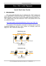
Power Input
CAN Port 1
CAN Port 2
Status LED of Power
& Communication
i-7531
CAN bus Repeater
‧Support CAN 2.0A/2.0B
‧Photo-isolation: 2500 Vrms
‧Expand the number of CAN buses
‧Mountable on DIN Rail
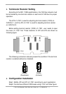
3000V Isolation
GND
11
(CAN)
20
CAN_L
CAN_H
FG
GND
10
(CAN)
1
CAN_L
CAN_H
FG
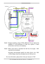
(R)VS+
(B)GND
Frame Ground
Frame Ground