


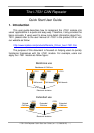
i-7531 CAN Repeater Quick Start User Guide (ver. 1.3, 2008/03/25) -----3
3. Terminator Resistor Setting
According to the ISO 11898 specifications, the CAN bus network must
be terminated by one terminal resistor on each end of CAN bus for proper
operation.
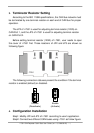
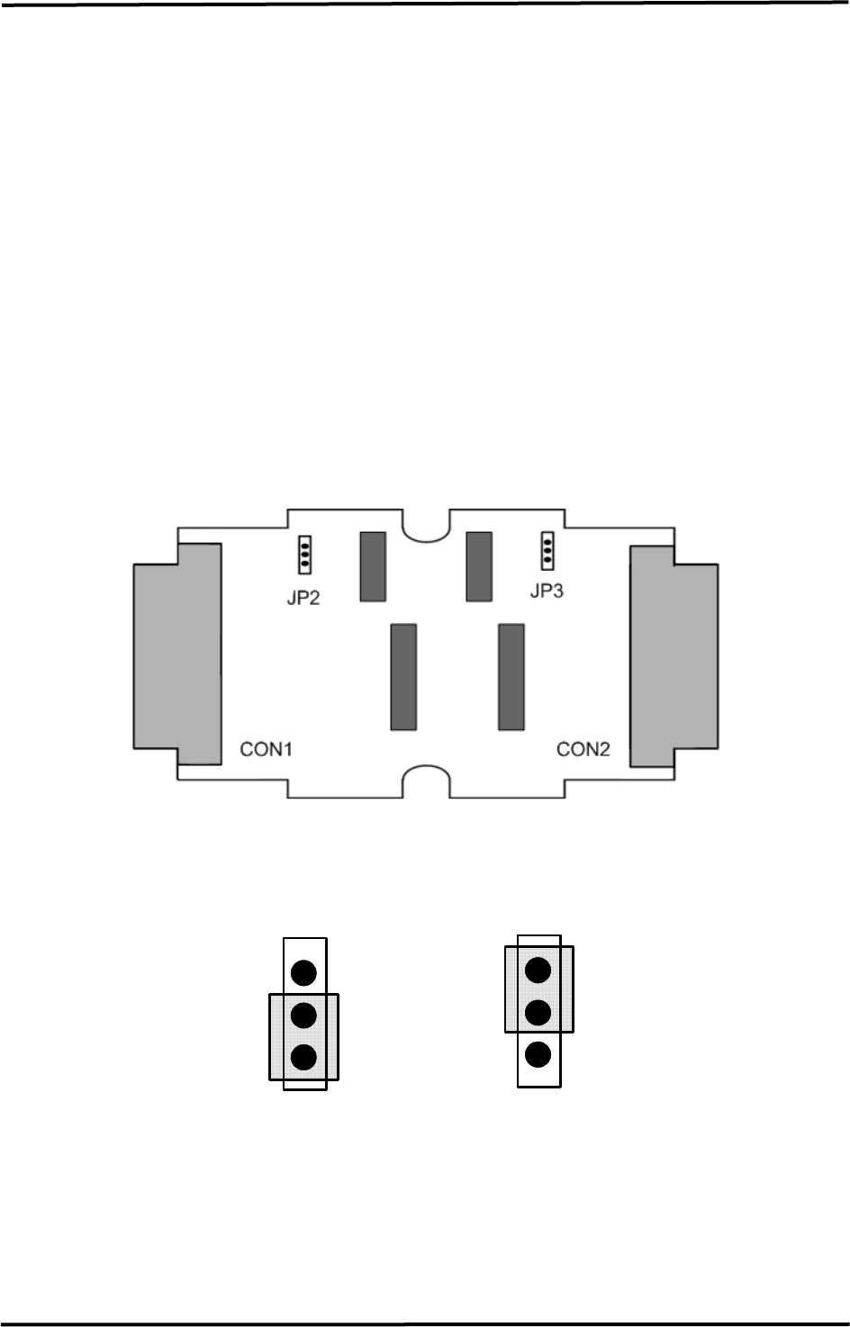
The JP2 of i-7531 is used for adjusting terminal resistor (120Ω) on
CAN Port 1, and the JP3 of i-7531 is used for adjusting terminal resistor
on CAN Port 2.
Before setting terminal resistor (120Ω) of i-7531, user needs to open
the cover of i-7531 first. Those locations of JP2 and JP3 are shown as
following figure:
The following connection statuses present the condition if the terminal
resistor is enabled (default) or disabled.
Disable
(Deactivate)
Enable
(Activate)
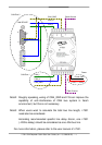
4. Configuration Installation
Step1: Modify JP2 and JP3 of i-7531 according to user’s application.
Step2: Connect two different CAN buses using i-7531 as follow figure: