696946.bok : 94601 2 Tue Apr 21 14:27:26 1998
C H A P T E R 1Quick Start
2
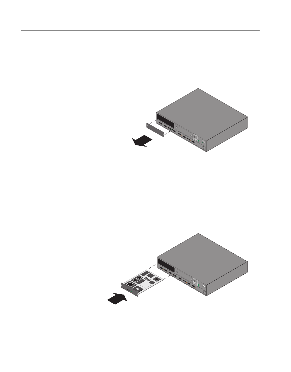
2 Turn off the power to the switch. Remove the plate covering the
slot on the Express 500 Series Switch.
Note For 510T, use Slot A. For 550T and 550F, use either
slot
3 Insert the Stack Interface Module into the slot. Place your
thumbs just beneath the screws on the front plate of the module
and push the module in until it clicks into position. Secure it
using the retaining screws.
Note If the module does not click into position, refer to the
Intel Support Web Page (http://support.intel.com) for
full instructions on how to install the module success-
fully.
4 Using another Express 500 Series Switch, repeat steps 1 to 3
with another Stack Interface Module.
1704
Blink
Solid
Solid
Off
Activity
Link
100 Mbps
10 Mbps
Collision
Disabled
Full duplex
Half duplex
LEDs
LEDs
Green
Green
Orange
Orange
Port Status
TX
TX
TX TX TX TX TX
TX
RXRX RX RX RX RX RX RX
123
87654
Slot B
Slot A
9600-8-N-1
Console
Intel Express
550F Switch
Power
Status
Temperature
RPS
Reset
Blink
Solid
Solid
Off
Activity
Link
100 Mbps
10 Mbps
Collision
Disabled
Full duplex
Half duplex
LEDs
LEDs
Green
Green
Orange
Orange
Port Status
TX
TX
TX TX TX TX TX
TX
RXRX RX RX RX RX RX RX
123
87654
Slot B
Slot A
9600-8-N-1
Console
Intel Express
550F Switch
Power
Status
Temperature
RPS
Reset
StackInterface Module for 500Series Switches


