


AUTOMOTIVE 80C51FA/83C51FA
PIN DESCRIPTIONS
V
CC
: Supply voltage.
V
SS
: Circuit ground.
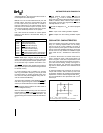
Port 0: Port 0 is an 8-bit, open drain, bidirectional
I/O port. As an output port each pin can sink several
LS TTL inputs. Port 0 pins that have 1's written to
them float, and in that state can be used as high-im-
pedance inputs.
Port 0 is also the multiplexed low-order address and
data bus during accesses to external Program and
Data Memory. In this application it uses strong inter-
nal pullups when emitting1's, and can source and
sink several LS TTL inputs.
Port 0 outputs the code bytes during program verifi-
cation. External pullup resistors are required during
program verification.
Port 1: Port 1 is an 8-bit bidirectional I/O port with
internal pullups. The Port 1 output buffers can drive
LS TTL inputs. Port 1 pins that have 1's written to
them are pulled high by the internal pullups, and in
that state can be used as inputs. As inputs, Port 1
pins that are externally pulled low will source current
(I
IL
, on the datasheet) because of the internal pull-
ups.
In addition, Port 1 serves the functions of the follow-
ing special features of the 83C51FA:
Port Pin Alternate Function
P1.0 T2 (External Count Input to Timer/
Counter 2)
P1.1 T2EX (Timer/Counter 2 Capture/
Reload Trigger and Direction Control)
P1.2 ECI (ExternalCount Input to the PCA)
P1.3 CEX0(External I/O for Compare/
Capture Module 0)
P1.4 CEX1(External I/O for Compare/
Capture Module 1)
P1.5 CEX2(External I/O for Compare/
Capture Module 2)
P1.6 CEX3(External I/O for Compare/
Capture Module 3)
P1.7 CEX4(External I/O for Compare/
Capture Module 4)
Port 2: Port 2 is an 8-bit bidirectional I/O port with
internal pullups. The Port 2 output buffers can drive
LS TTL inputs. Port 2 pins that have 1's written to
them are pulled high by the internal pullups, and in
that state can be used as inputs. As inputs, Port 2
pins that are externally pulled low will source current
(I
IL
, on the datasheet) because of the internal pull-
ups.
Port 2 emits the high-order address byte during
fetches from external Program Memory and during
accesses to external Data Memory that use 16-bit
addresses (MOVX
DPTR). In this application it
uses strong internal pullups when emitting 1's. Dur-
ing accesses to external Data Memory that use 8-bit
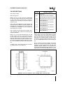
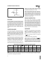
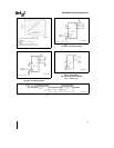
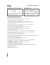
Pin (PDIP)
270501±3
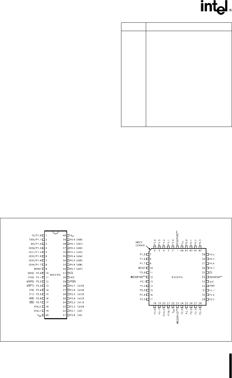
Pad (PLCC)
270501±4
Do not connect reserved pins.
Diagrams are for pin reference only. Package sizes are not to scale.
Figure 3. Pin Connections
4