


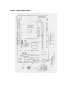
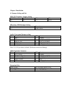
Connectors
PS/2 (Bottom) PS/2 Keyboard (Down Purple)
PS/2 (Top) PS/2 Mouse Header (Up Green)
USB 0/1 USB 0/1 Connector Port
USB 2/3 USB 2/3 Connector Port
LPT Printer Connector Port
VGA VGA Display Connector Port
COM1 Serial Ports COM1 Connector Port
GAME/MIDI Game/MIDI Port
LINE OUT/LINE IN/MIC Audio Output/Audio Input/Microphone
CD_IN CD-ROM Audio Input Port
IDE1/IDE2 Primary IDE/Secondary IDE Port
FDD Floppy Disk Drive Connector Port
PW1 ATX_20 Power Supply Connector Port
PW2 ATX_4 Power Supply Connector Port
FAN ½ CPU System Fan Port
IrDA IrDA Infrared Port
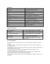
Function Port Pane1
Power Supply LED Pin 1:Power Supply Anode; Pin 3: Ground
HDD LED Pin 2: Power Supply Anode; Pin 4: LED Signal
ATX Power Supply Switch Pin 8: Switch Signal; Pin 10: Power Supply
Anode
Reset Switch Pin 14: Ground; Pin 16:Reset Signal
Speaker Input Pin 9: Speaker Audio Input; Pin 15 : Power
Supply Anode
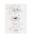
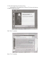
4.2 CPU Installation
This main board has a socket 478 processor socket. Follow these instructions to install
the CPU:
1. Unhook the CPU socket’s locking lever pulling it away from socket and raising it to
the upright position.
2. Match the pin 1 corner of CPU socket to the one of processor, and insert the processor
into the socket. Do not use force.
3. Push the locking lever down and hook it under the latch on the edge of socket.
4. Apply thermal grease to the top of the CPU.
5. Lower the CPU fan/heat sink unit onto the CPU and CPU socket, and then use the
retention module clamps to snap the fan/heat sink into place.
6. Plug the CPU fan power cable into the CPU cooling fan power supply connector on the
main board.