


INSTALLATIONS
IB865 User’s Manual 23
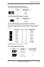
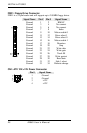
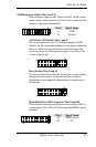
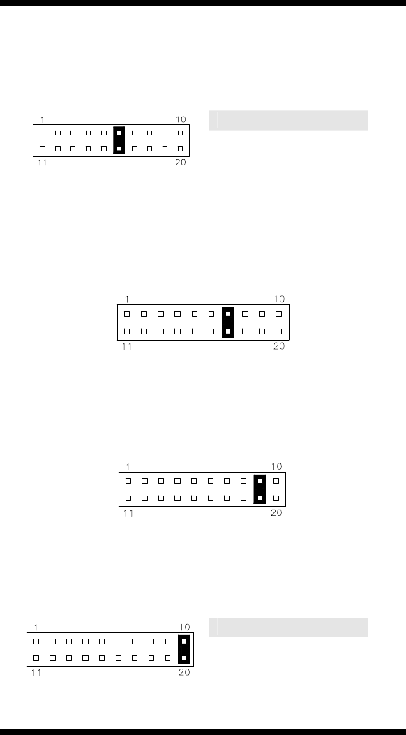
SMI/Hardware Switch: Pins 6 and 16
This connector supports the "Green Switch" on the control
panel, which, when pressed, will force the system into the
power-saving mode immediately.
Pin #
Signal Name
6 SMI
16 Ground
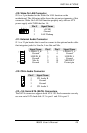
ATX Power ON Switch: Pins 7 and 17
This 2-pin connector is an “ATX Power Supply On/Off
Switch” on the system that connects to the power switch on
the case. When pressed, the power switch will force the
system to power on. When pressed again, it will force the
system to power off.
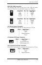
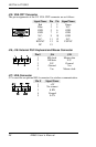
Reset Switch: Pins 9 and 19
The reset switch allows the user to reset the system without
turning the main power switch off and then on again.
Orientation is not required when making a connection to
this header.
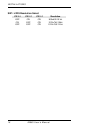
Hard Disk Drive LED Connector: Pins 10 and 20
This connector connects to the hard drive activity LED on
control panel. This LED will flash when the HDD is being
accessed.
Pin # Signal Name
10 HDD Active
20 5V