


INSTALLATIONS
IB865 User’s Manual 25
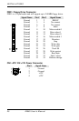
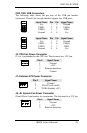
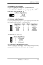
J10: Wake On LAN Connector
J10 is a 3-pin header for the Wake On LAN function on the
motherboard. The following table shows the pin out assignments of this
connector. Wake On LAN will function properly only with an ATX
power supply with 5VSB that has 1A.
Pin # Signal Name
1 +5VSB
2 Ground
3 LAN Wakeup
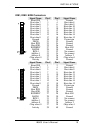
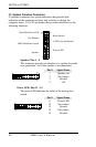
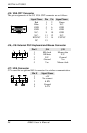
J11: External Audio Connector
J11 is a 12-pin header that is used to connect to the optional audio cable
that integrates jacks for Line In, Line Out and Mic.
Signal Name Pin # Pin # Signal Name
LINEOUT_R 1 2 LINEOUT_L
Ground 3 4 Ground
LINEIN_R 5 6 LINEIN L
Ground 7 8 Ground
Mic-In 9 10 VREFOUT
Ground 11 12 Protect pin
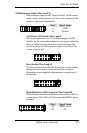
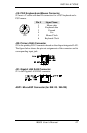
J12: CD-In Audio Connector
Pin # Signal Name
1 CD Audio R
2 Ground
3 Ground
4 CD Audio L
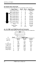
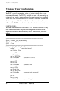
J13, J14: Serial ATA (SATA) Connectors
The SATA connectors support serial ATA 150. Each connector can only
use one serial ATA hard disk. J13 is port 1 and J14 is port 2.