


NVM Information Guide—ICH8
16
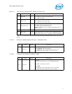
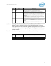
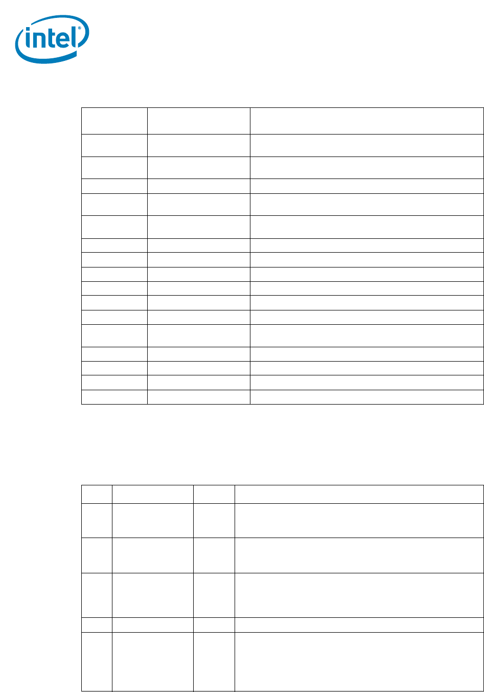
1.4.20 LED 0 and 2 Configuration Defaults (Word 18h)
This NVM word specifies the hardware defaults for the LEDCTL register fields controlling
the LED0 (LINK/ACTIVITY) and LED2 (LINK_100) output behaviors.
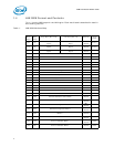
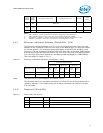
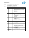
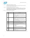
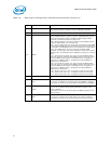
Table 16. LED Modes
Mode (Bits
3:0)
Selected Mode Source Indication
0000b LINK_10/1000
Asserted when either 10 Mb/s or 1000 Mb/s link is established
and maintained.
0001b LINK_100/1000
Asserted when either 100 Mb/s or 1000 Mb/s link is
established and maintained.
0010b LINK-UP Asserted when any speed link is established and maintained.
0011b FILTER_ACTIVITY
Asserted when link is established and packets are being
transmitted or received that passed MAC filtering.
0100b LINK/ACTIVITY
Asserted when link is established and when there is no
transmit or receive activity.
0101b LINK_10 Asserted when a 10 Mb/s link is established and maintained.
0110b LINK_100 Asserted when a 100 Mb/s link is established and maintained.
0111b LINK_1000 Asserted when a 1000 Mb/s link is established and maintained.
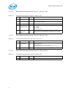
1000b Reserved Reserved.
1001b FULL_DUPLEX Asserted when the link is configured for full duplex operation.
1010b COLLISION Asserted when a collision is observed.
1011b ACTIVITY
Asserted when link is established and packets are being
transmitted or received.
1100b BUS_SIZE Asserted when the MAC detects a 1-lane PCIe* connection.
1101b PAUSED Asserted when the MAC transmitter is flow controlled.
1110b LED_ON Always asserted.
1111b LED_OFF Always de-asserted.
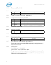
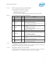
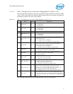
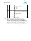
Table 17. LED 0 and 2 Configuration Defaults (Word 18h)
Bit Name Default Description
15 LED2 Blink 0b
This bit indicates the initial value of the LED2_BLINK field.
0b = LED2 is non-blinking.
1b = LED2 is blinking.
14 LED2 Invert 0b
This bit indicates the initial value of the LED2_IVRT field.
0b = LED2 has an active low output.
1b = LED2 has an active high output.
13 LED2 Blink Mode 0b
This bit defines the LED2 blink mode:
0b = Blink at 200 ms on and 200 ms off.
1b = Blink at 83 ms on and 83 ms off.
Note: This field should be identical to the LED0 Blink Mode.
12 Reserved 0b This bit is reserved and should be set to 0b.
11:8 LED2 Mode 0110b
These bits represent the initial value of the LED2_MODE field,
which specifies the event, state, or pattern displayed on LED2
(LINK_100) output. A value of 0110b causes this to indicate
100 Mb/s operation.