


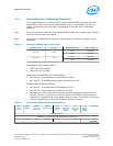


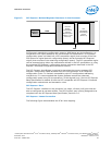
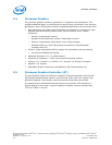


Figure 3. PCI Express* Related Register Structures in the Processor
PCI-PCI
Bridge
representing
root PCI
Express ports
(Device 1 and
Device 6)
PCI
Compatible
Host Bridge
Device
(Device 0)
PCI
Express*
Device
PEG0
DMI
PCI Express* extends the configuration space to 4096 bytes per-device/function, as
compared to 256 bytes allowed by the conventional PCI specification. PCI Express*
configuration space is divided into a PCI-compatible region (that consists of the first
256 bytes of a logical device's configuration space) and an extended PCI Express*
region (that consists of the remaining configuration space). The PCI-compatible region
can be accessed using either the mechanisms defined in the PCI specification or using
the enhanced PCI Express* configuration access mechanism described in the PCI
Express* Enhanced Configuration Mechanism section.
The PCI Express* Host Bridge is required to translate the memory-mapped PCI
Express* configuration space accesses from the host processor to PCI Express*
configuration cycles. To maintain compatibility with PCI configuration addressing
mechanisms, it is recommended that system software access the enhanced
configuration space using 32-bit operations (32-bit aligned) only. See the PCI Express
Base Specification for details of both the PCI-compatible and PCI Express* Enhanced
configuration mechanisms and transaction rules.
PCI Express* Port
The PCI Express* interface on the processor is a single, 16-lane (x16) port that can
also be configured at narrower widths. The PCI Express* port is being designed to be
compliant with the PCI Express Base Specification, Revision 3.0.
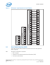
PCI Express* Lanes Connection
The following figure demonstrates the PCIe* lane mapping.
Interfaces—Processor
Desktop 4th Generation Intel
®
Core
™
Processor Family, Desktop Intel
®
Pentium
®
Processor Family, and Desktop Intel
®
Celeron
®
Processor Family
December 2013 Datasheet – Volume 1 of 2
Order No.: 328897-004 25