


7.0 Electrical Specifications
This chapter provides the processor electrical specifications including integrated
voltage regulator (VR), V
CC
Voltage Identification (VID), reserved and unused signals,
signal groups, Test Access Points (TAP), and DC specifications.
Integrated Voltage Regulator
A new feature to the processor is the integration of platform voltage regulators into
the processor. Due to this integration, the processor has one main voltage rail (V
CC
)
and a voltage rail for the memory interface (V
DDQ
) , compared to six voltage rails on
previous processors. The V
CC
voltage rail will supply the integrated voltage regulators
which in turn will regulate to the appropriate voltages for the cores, cache, system
agent, and graphics. This integration allows the processor to better control on-die
voltages to optimize between performance and power savings. The processor V
CC
rail
will remain a VID-based voltage with a loadline similar to the core voltage rail (also
called V
CC
) in previous processors.
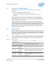
Power and Ground Lands
The processor has VCC, VDDQ, and VSS (ground) lands for on-chip power distribution.
All power lands must be connected to their respective processor power planes; all VSS
lands must be connected to the system ground plane. Use of multiple power and
ground planes is recommended to reduce I*R drop. The VCC lands must be supplied
with the voltage determined by the processor Serial Voltage IDentification (SVID)
interface. Table 45 on page 91 specifies the voltage level for the various VIDs.
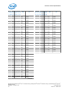
V
CC
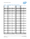
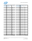
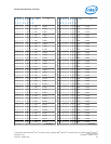
Voltage Identification (VID)
The processor uses three signals for the serial voltage identification interface to
support automatic selection of voltages. The following table specifies the voltage level
corresponding to the 8-bit VID value transmitted over serial VID. A ‘1’ in this table
refers to a high voltage level and a ‘0’ refers to a low voltage level. If the voltage
regulation circuit cannot supply the voltage that is requested, the voltage regulator
must disable itself. VID signals are CMOS push/pull drivers. See Table 53 on page
102 for the DC specifications for these signals. The VID codes will change due to
temperature and/or current load changes to minimize the power of the part. A voltage
range is provided in Voltage and Current Specifications on page 98. The
specifications are set so that one voltage regulator can operate with all supported
frequencies.
Individual processor VID values may be set during manufacturing so that two devices
at the same core frequency may have different default VID settings. This is shown in
the VID range values in Voltage and Current Specifications on page 98. The
processor provides the ability to operate while transitioning to an adjacent VID and its
associated voltage. This will represent a DC shift in the loadline.
7.1
7.2
7.3
Processor—Electrical Specifications
Desktop 4th Generation Intel
®
Core
™
Processor Family, Desktop Intel
®
Pentium
®
Processor Family, and Desktop Intel
®
Celeron
®
Processor Family
Datasheet – Volume 1 of 2 December 2013
90 Order No.: 328897-004