


21
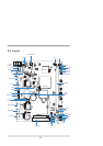
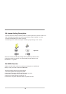
3-1 List of Connectors
This chapter provides all necessary information of the peripheral's connections,
switches and indicators. Always power off the board before you install the peripherals.
Chapter-3
Connection
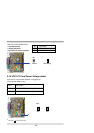
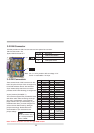
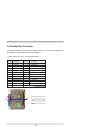
CN1: DC 12V-IN DIN Connector
CN4: DC 12V-IN Connector (Share to CN1)
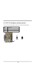
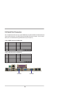
CN5: PS2 Keyboard /Mouse Connector
JKM1: PS2 Keyboard /Mouse Connector (Share to CN5)
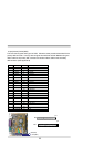
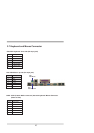
CN3: USB port 0/1 and LAN1 RJ45 Connector(or CN11 single RJ45)
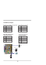
CN7: COM1 port Connector
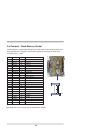
CN2: VGA DB15 Connector
CN46: VGA Header
CN10: Printer (LPT)port
CN6: COM2 port Connector
CN9: LAN2 RJ45 Connector
CN8: LAN3 RJ45 Connector
CN19: IDE1 40 pin (2.54mm)Connector
CN18: IDE2 44 pin (2.0mm)Connector
CN20:CF 50 pin socket
SATA1: S-ATA IDE 7pin Wafer
CN14: USB port 2 connector
CN16: USB port 3 connector
CN27: USB port 4 connector
JUSB1/JUSB2:USB 4/5 port connector
CN29: Line out connector
CN28 : Mic-in connector
CN47: Line out /Line in/ Mic-in Header
JF2: CPU FAN connector
JF1: System FAN connector
JI1: IR connector
CN21: DC +5/+12V output connector
CN26: I2C Bus connector
CN13: TV out connector
MPCI1:Mini PCI socket
JR1: Reset pin
SW1 : System power switch
JSW1 : System power switch pin header
PW LED : System power LED or pin header
JP1: System power LED pin header
HD LED : Hard Disk LED or pin header
LAN LED: LAN active LED