


34
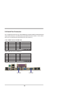
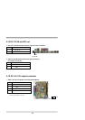
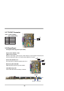
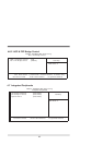
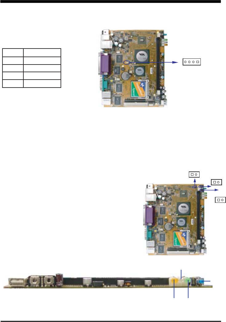
3-18 Front-Panel
. JR1: System Reset key( 2.0mm pin header)
. Power switch: PW-ON--- SW1
JSW1: Power on switch
Based on case design , there may be a power switch or a 2-pin header connected to the
case-mounted power switch. It is used to power ON/OFF the system.
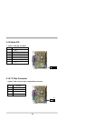
. Power LED: PW-LED / JP1
The Power LED is lit while the system power is on.
. IDE Activity LED: HDD-LED
HDD-LED shows the activity of the hard disk.
. LAN LED Activity LED
LAN1/ LAN2 LED shows the activity of network
SW1
HDD LED
LAN LED
Power LED
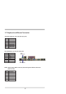
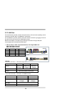
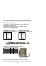
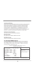
3-17 TV-OUT Connector
CN13 : TV-OUT S-VIDEO
(4pin 1.25mm Wafer)
PIN NO. Description
1 LUMA-out
2 CHROMA-out
3 CVBS
4 GND
CN13
pin1
JR1
pin1
JP1
pin1
JSW1
pin1