


22
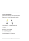
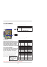
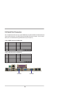
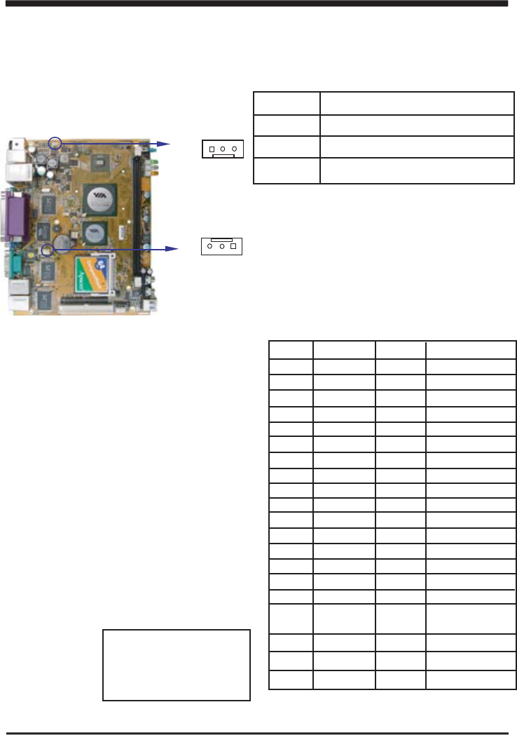
3-2 FAN Connector
CV700A provides one CPU fan connector and one system fan connector.
CPU Fan Connector- JF2
System FAN Connector-JF1
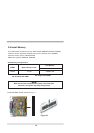
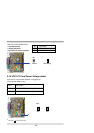
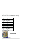
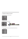
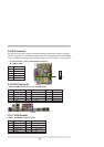
3-3 IDE Connectors
There are two kinds of IDE connectors on this
board, 40-pin and 44-pin. Each can support up
to two IDE-inferface devices. One standard
40-pin header daisy-chain driver connector
provides as IDE1 with following pin assignment.
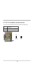
40 pins (2.54mm)-CN19(IDE 1)
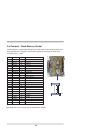
This connector supports the provided IDE hard
disk ribbon cable. After connecting the single
plug end to motherboard, connect the two
plugs at other end to your hard disk(s). If you
install two hard disks, you must configure the
second drive as Slave mode by setting its
jumpers accordingly. Please refer to the
documentation of your hard disk for the
jumper settings.
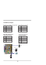
PIN NO. Description
1 FAN Control ON/OFF
2 +12V
3 FAN speed Sensor
PIN NO. Description PIN NO. Description
1 RESET# 2 GROUND
3 DATA7 4 DATA8
5 DATA6 6 DATA9
7 DATA5 8 DATA10
9 DATA4 10 DATA11
11 DATA3 12 DATA12
13 DATA2 14 DATA13
15 DATA1 16 DATA14
17 DATA0 18 DATA15
19
21
23
25
27
29
31
33 SA 1 34 ATA 33/66/100
CABLE SELECT
GROUND
DREQ
IOW#
IOR#
IORDY
DACK#
IRQ14
20
22
24
26
28
30
32
+5V
GROUND
GROUND
GROUND
PULL DOWN
GROUND
NC
35
36
40
37
39
38
SA 0
SA 2
HD CS0#
HD LED
HD CS1#
GROUND
pin1
JF2
pin1
JF1
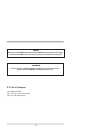
Note: Pin20 is +5V power can use new type DOM module.
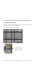
*Note : DC- in +12V by switch to DC-out voltage +12V
So DC -in need stable +12V input
Note!
PIN 20 connector +5V of
IDE 1 could provide the
power of DOM