


Contents
v
5 Technical Reference
Board Connectors ...............................................................................................................67
Back Panel Connectors ..............................................................................................68
Midboard Connectors .................................................................................................69
Front Panel Connectors..............................................................................................73
Desktop Board Resources...................................................................................................74
Memory Map ..............................................................................................................74
DMA Channels ...........................................................................................................74
I/O Map ......................................................................................................................75
Interrupts....................................................................................................................77
A Error Messages and Indicators
BIOS Beep Codes...............................................................................................................79
BIOS Error Messages .........................................................................................................80
B Regulatory Compliance
Safety Regulations ..............................................................................................................83
EMC Regulations ................................................................................................................83
Product Certification Markings.............................................................................................84
Installation Precautions .......................................................................................................85
Installation Instructions........................................................................................................85
Ensure Electromagnetic Compatibility (EMC) Compliance .........................................86
Chassis and Component Certifications.......................................................................86
Prevent Power Supply Overload.................................................................................86
Place Battery Marking ................................................................................................87
Use Only for Intended Applications.............................................................................87
Figures
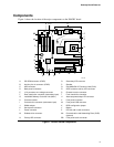
1. D845HV Board Components.......................................................................................... 9
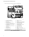
2. D845WN Board Components........................................................................................10
3. Location of Standby Power Indicator.............................................................................18
4. Installing the I/O Shield.................................................................................................22
5. D845HV Board Mounting Holes ....................................................................................23
6. D845WN Board Mounting Holes ...................................................................................24
7. Processor Fan Heatsink RM Mounting Holes................................................................25
8. Installing the Processor Fan Heatsink RM Base to the Board.......................................26
9. Installing a Processor....................................................................................................27
10. Connecting the Processor Fan Heatsink Cable to the Processor Fan Connector .........28
11. Installing a Memory Module..........................................................................................30
12. AGP Card with Retention Notch....................................................................................32
13. Installing the AGP Card Retention Mechanism .............................................................33
14. Removing the AGP Card ..............................................................................................34
15. Removing the AGP Card Retention Mechanism ...........................................................35
16. Connecting the IDE Cable.............................................................................................36
17. Location of the BIOS Configuration Jumper Block ........................................................37
18. Removing the Battery ...................................................................................................41
19. Back Panel Connectors ................................................................................................68
20. Audio Connectors .........................................................................................................69