


Contents
vii
Chipset Configuration Submenu .................................................................................68
Fan Control Submenu.................................................................................................70
Hardware Monitoring Submenu ..................................................................................71
Security Menu .....................................................................................................................72
Power Menu........................................................................................................................73
ACPI Submenu...........................................................................................................74
Boot Menu...........................................................................................................................75
Boot Device Priority Submenu....................................................................................76
Hard Disk Drives Submenu.........................................................................................77
Removable Devices Submenu....................................................................................78
ATAPI CD-ROM Drives ..............................................................................................79
Exit Menu ............................................................................................................................80
5 Technical Reference
Board Connectors ...............................................................................................................81
Back Panel Connectors ..............................................................................................82
Audio Connectors .......................................................................................................83
Add-In Card and Peripheral Interface Connectors ......................................................84
Desktop Board Resources...................................................................................................85
Memory Map ..............................................................................................................85
DMA Channels ...........................................................................................................85
Interrupts ....................................................................................................................86
A Error Messages and Indicators
BIOS Beep Codes ...............................................................................................................87
BIOS Error Messages..........................................................................................................88
B Regulatory Compliance
Safety Regulations ..............................................................................................................91
EMC Regulations ................................................................................................................91
Product Certification Markings.............................................................................................92
Figures
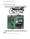
1. Desktop Board D865GBF Components ........................................................................12
2. Location of Standby Power Indicator.............................................................................22
3. Installing the I/O Shield .................................................................................................28
4. Location of Desktop Board Mounting Screw Holes........................................................29
5. Installing a Processor....................................................................................................30
6. Connecting the Processor Fan Heat Sink Cable to the Processor Fan Connector ........31
7. Installing a Memory Module ..........................................................................................32
8. Dual Configuration Example with Two DIMMs ..............................................................33
9. Dual Configuration Example with Four DIMMs..............................................................33
10. Removing the AGP Card...............................................................................................35
11. Connecting the IDE Cable.............................................................................................36
12. Connecting the Serial ATA Cable..................................................................................37
13. Internal Headers ...........................................................................................................38
14. Back Panel Audio Connectors for 6-Channel Audio with Jack Sensing.........................40
15. Location of Hardware Control Headers and Power Connectors ....................................42
16. Location of the BIOS Configuration Jumper Block.........................................................44
17. Removing the Battery ...................................................................................................48